33
6. Description of Additional Functions
Areas of Caution Before Use
(1) Check that the wiring is set up so that the motor is rotating in reverse (REV) when lowering, and
forward (FWD) when hoisting in all control modes.
(2) Be sure to set S1-20 to "1" (enabling regen operation while the motor is rotating) when using the
crane to lower or hoist the load without a counter-weight (necessary only when running in Open Loop
Vector Control Mode).
Parameter S1-20 can be changed after setting the Access Level to "Advanced" (A1-02 = 4).
(3) For safety, be sure overspeed detection and slip -down detection are set up properly.
6.1 Brake Sequence
For the brake to both clamp and release while maintaining the torque appropriate for the load when starting or stopping,
the brake release command is output based on the size of the torque reference, motor current, or frequency reference
internal to the drive.
Operation Description
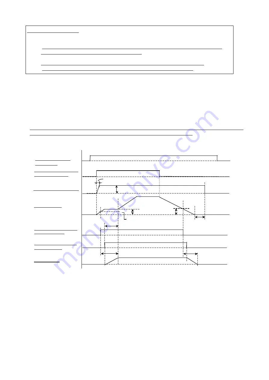
A time chart and the terminal functions are shown below when running the drive via the external terminals , once
b1-01 and b1-02 have both been set to "1" (Frequency Reference Selection and Run Command Selection
respectively).
Refer to the "Compatibility Diagram" to make sure the brake sequence operates as described: when the brake release
command is closed, then the brake is released; when the relay is open, the brake is applied.
Flux Vector Mode
Note: 1: Areas to take note of when setting parameters:
・
Set the Slip Prevention Time HT (S1 -15) to “0” (default), and the Stop Timer ST (b2-04) must be equal to=
(Brake Delay Time).
・
Default setting for BT and BF is zero when operating in Vector with PG mode.
Note 2: Areas of caution when dealing with Torque Compensation:
・
An application in which a counter-weight is not needed for hoisting is used when a faster brake release
time (shortening the operation cycle) or brake release with a low output frequency (jolt/jerk free operation)
is desired. Here, the Brake Release Frequency FRF and FRR are set to zero.
・
Torque compensation can be input from analog terminal A2 by setting parameters S1-09 and S1-10, as
well as H3-09 to "14". When using analog input, the amount of torque compensation is latched when the
forward (reverse) run command input.
・
The Torque Compensation Delay Time (ITCT) is the time, it takes for the amount of torque compensation
to change from 0% to 100% (i.e., the setting time is 1/2 when the amount of torque
compensation is at
50%).
FHF (FHR)
ITCF (ITCR)
closed
open
ITC
T
BT
BF
FRF (FRR)
ST
closed
open
closed
open
BDT
BDT
open
closed
BT
↑
↓
Speed Command Input
(Terminal A1)
Forward (Reverse) Command
Input Terminal S1, S2
Torque Compensation Amount
Output Frequency
Brake Release Command BR
(Terminal M1-M2)
Brake Release Answer Back
BX (Terminal S5)
Brake Operation
Summary of Contents for CIMR-F7Z
Page 3: ......


