


16
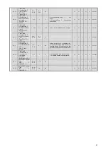
L4-04
Speed Agreement
Detection Width
(+/-)
(Spd Agree Width
+-)
0.0~
20.0
0.1
Hz
2.0
N
A
A
A
A
49CH
L4-05
Operation When
Frequency
Reference is
Missing
(Ref Loss Sel)
0,1
1
0
0: Controls disabled during freq.
reference loss.
1: Controls enabled during freq.
reference loss whth L4-06 fref.
N
A
A
A
A
49DH
L4-06
Frequency
reference when
freq missing
(Fref at Floss)
0.0~
100.0
0.1%
80
When L4-05 is set to 1, L4-05 setting
becomes the frequency reference when
freq reference missing.
N
A
A
A
A
4C2H
Note-5: In Flux Vector Control Mode (A1-02 = 03), the setting value "3" cannot be used (Stall Prevention with Braking Resistor).
Table 4.2.2 Parameter Table (10)
Parameter Access Level
Note-2
Function
No.
Parameter Name
(Digital Operator
Display)
Setting
Range
Setting
Units
Factory
Settings
Comments
Chan
ges
on
the
Fly
V/f
V/f
w/P
G
OLV CLV
Memo
bus
Address
L7-01
Forward Drive
Torque Limit
(Torq Limit
Fwd)
0~300
1%
200
N
N
N
A
A
4A7H
L7-02
Reverse Drive
Torque Limit
(Torq Limit
Rev)
0~300
1%
200
N
N
N
A
A
4A8H
L7-03
Forward
Regenerative
Torque Limit
(Torq Lmt Fwd
Rgn)
0~300
1%
200
N
N
N
A
A
4A9H
L7-04
Reverse
Regenerative
Torque Limit
(Torq Lmt Rev
Rgn)
0~300
1%
200
N
N
N
A
A
4AAH
L7-06
Integral Time
Setting for
Torque Limit
(Torq Limit
Time)
5~
10000
1
ms
200
ms
N
N
N
A
N
4ACH
Torque Limit
L7-07
Control Method
Selection for
Torque Limit
During
Acceleration
Deceleration
(Torque Limit
sel)
0,1
1
0
Selects the method of torque limit
controls during accel/decel
0: Proportional Controls (uses
integral controls at fixed speeds).
1: Integral Controls
N
N
N
A
N
4C9H
L8-01
Protect
Selection for
Internal DB
Resistor (Type
ERF)
(DB Resistor
Prot)
0,1
1
0
0: Internal Braking Resistance not
provided.
1: Internal Braking Resistance
provided.
N
A
A
A
A
4ADH
L8-02
Overheat
Pre-Alarm Level
(OH Pre-Alarm
Lvl)
50~
130
1
deg
95
*
* Factory/default settings will vary
based on drive capacity (refer to
attached table).
N
A
A
A
A
4AEH
L8-03
Operation
Selection After
Overheat
Pre-Alarm
(OH Pre-Alarm
sel)
0~3
1
3
0: Deceleration Stop 2: Fast Stop
1: Coast to Stop 3: Alarm Only
N
A
A
A
A
4AFH
L8-05
Input
Open-Phase
protection
Selection
(Ph Loss In Sel)
0,1
1
1
0: Input Phase Protection disabled.
1: Input Phase Protection enabeld.
N
A
A
A
A
4B1H
L8-07
Output
Open-Phase
protection
Selection
(Ph Loss Out
Sel)
0~2
1
1
0: Disabled
1: 1-phase Loss Detection
2: 2/3 -phase Loss Detection
N
A
A
A
A
4B3H
Hardware Protection
L8-08
Output
Open-Phase
Detection Level
(Ph Loss Out
Lvl)
0.0~
20.0
0.01%
5.0
N
A
A
A
A
4B4H
Summary of Contents for CIMR-F7Z
Page 3: ......