


8 CC-Link Data Table
44
YASKAWA ELECTRIC
TOBP C730600 83C YASKAWA AC Drive Option SI-C3 Installation Manual
u
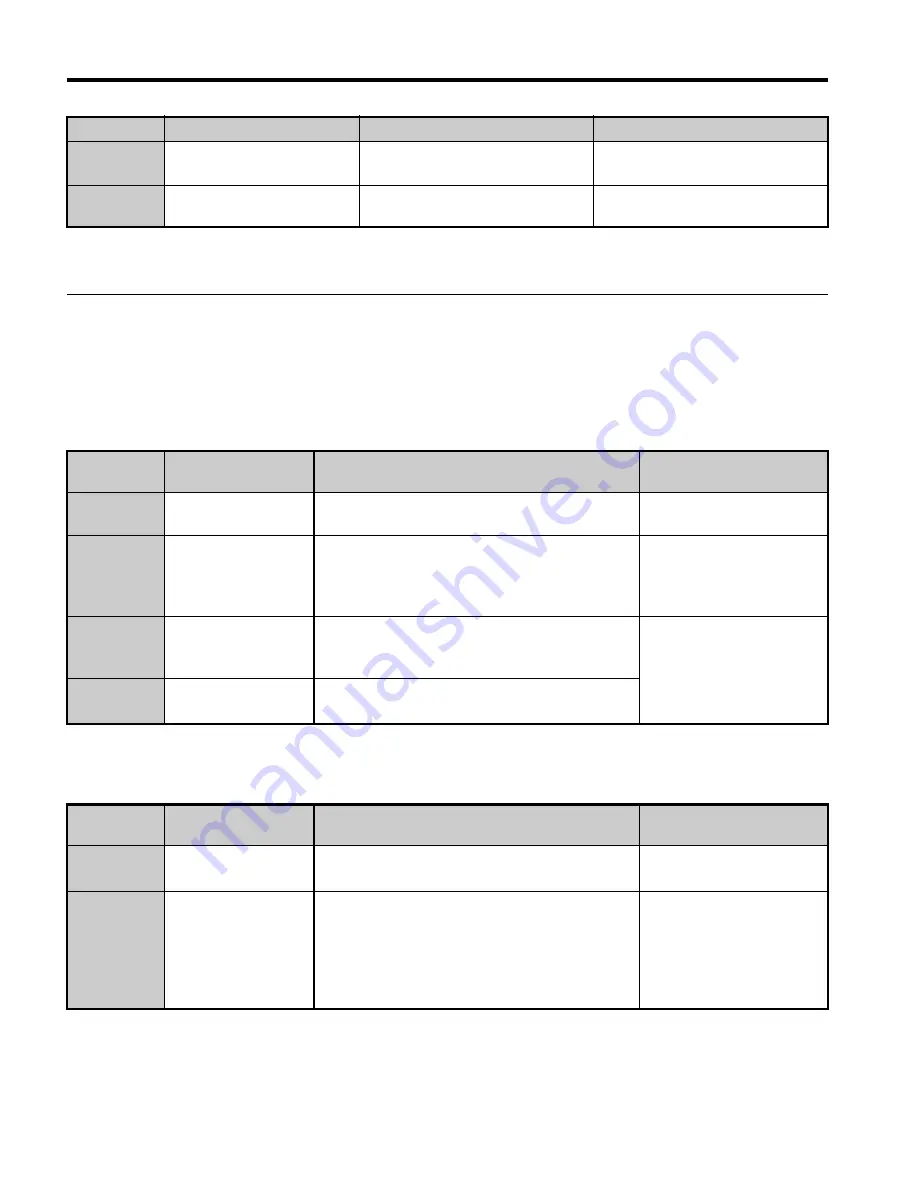
Remote Register
Note:
Remote register data varies between drives and energy-saving units.
n
Drive Remote Register
PLC
→
Drive
Table 13 Remote Register (PLC
→
Drive)
Drive
→
PLC
Table 14 Remote Register (Drive
→
PLC)
RX1B
Remote Station Ready
ON: Energy-saving unit is ready to
operate.
–
RX1C
to 1F
Reserved
–
–
<1> Terminals will differ depending on the model of the drive. Refer to
Terminals that Change depending on the
Model of the Drive on page 46
for information on terminals.
Remote
Register
Name
Description
Request Flag
RW
W0
Monitor Code
Sets the code number of the items to be
displayed by the monitor.
RYC (Monitor Execute
Request)
RW
W1
Frequency Setting
Specifies the source of the frequency reference.
• RYD (Frequency
Reference 1)
• RYE (Frequency
Reference 2)
RW
W2
Command Code
Sets the command code to execute functions
such as the fault reset, fault history, parameter
read, and so on.
RYF (Command Code
Execute Request)
RW
W3
Write Data
Sets the value to be used along with RW
W2
(Command Code) as needed.
Remote
Register
Name
Description
Check Flag
RW
R0
Monitor Data
Monitor data is stored according to RW
W0
(Monitor Code).
RXC (while monitoring)
RW
R1
Output Frequency
Motor revolutions or output frequency has been
set without errors.
Sets data contents with RYB (Motor
Revolutions/Output Frequency Switch).
Set in the drives specified by o1-03 (Frequency
Reference Setting Drives) in output frequency.
RXB (actual motor
rotations)
Device
Name
Description
Default
TOBP_C730600_83C_3_0_E.fm 44 ページ 2018年10月24日 水曜日 午後5時59分


