1.
Build-up each for the master and slave side a SLIO system, which both contain a
CP 040.
2.
Connect both systems via the serial interface.
3.
Configure the master section.
The configuration of the CP 040 as Modbus master happens via the hardware con-
figuration. In addition you need a PLC user application for the communication with
the following structure:
OB 100: One-time call of the handling blocks FB 60 - SEND and FB 61 - RECEIVE
(or FB 65 SEND_RECV) with all parameters and set R for initialization.
OB 1: Call of FB 60 - SEND (or FB 65 SEND_RECV) with error evaluation. For this
the telegram is to be stored in the send block according to the Modbus rules. Call of
FB 61 - RECEIVE with error evaluation. The data are stored in the receive block
according to Modbus rules.
4.
Configure the slave section.
The parameterization of the CP 040 happens via the hardware configuration. Enter
here the start address for the in- and output area from where on, depending on the
IO Size, the input and output data are stored in the CPU.
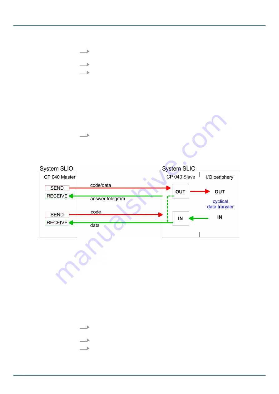
Modbus Master
The communication in master mode happens via data blocks deploying the CP 040 han-
dling blocks FB 60 - SEND and FB 61 - RECEIVE (or FB 65 SEND_RECV). Here you can
transfer up to 250byte user data.
Modbus Slave long
In the Modbus Slave long mode only a changed data area is transferred to the CPU via
FB 61 - RECEIVE starting with 0. If the master requests data it has to be made sure that
the relevant data are present in the CP. With a FB 60 - SEND call a wanted data area is
transferred to the CP starting with 0.
1.
Build-up each for the master and slave side a SLIO system, which both contain a
CP 040.
2.
Connect both systems via the serial interface.
3.
Configure the master section.
The project engineering of the master section happens like shown in the sample
above.
Approach
Master
n
Slave long
Approach
VIPA System SLIO
Serial communication protocols
Deployment - Modbus > Modbus - Overview
HB300 | CP | 040-1CA00 | en | 18-28
80


