4. ENGINE
4-2-5
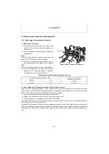
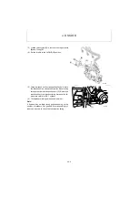
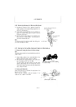
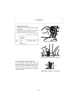
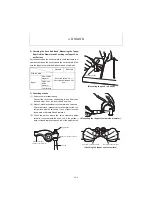
3) Nozzle Valve Sliding Test
Thoroughly wash the nozzle valve using clean fuel. Hold the nozzle
body vertical, and put the nozzle valve approx. 1 / 3 of its length into
the body.
Check if the nozzle valve falls smoothly by self-weight when released.
If so, the nozzle valve is good. In case of a new nozzle, remove the
seal peel, and immerse it in clean light oil or the like to clean its inner
and outer surfaces and thoroughly remove rust-preventive oil before
using the nozzle. Note that a new nozzle is immersed in rust-preven-
tive oil and then is pasted with a seal peel to shut off the outside air.
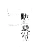
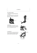
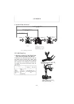
4) Nozzle Body Identification Number
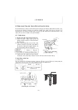
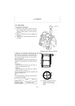
4-2-5 Checking and Adjusting Fuel Injection Timing
Note:
The following procedure is performed on the No. 1 cylinder. While checking and adjusting the timing on only No. 1
cylinder is usually sufficient, the same procedure can be performed on any or all cylinders.
1) Checking Fuel Injection Timing
Note:
Some fuel may drain from the fuel injection pump during this process. Make provisions to contain and dispose of any
such spillage.
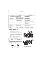
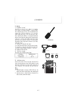
(1) Turn the key switch to the ON position for 10 to 15 seconds. This will allow the fuel transfer pump to prime the
fuel system.
Note:
Never use the starter motor to prime the fuel system. This may cause the starter motor to overheat and damage the
coils, pinion gear and / or ring gear.
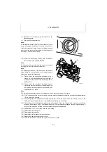
(2) Clean the area around the fuel injection pump.
Note:
The stop solenoid must be removed to allow fuel to flow through the fuel injection pump.
(Nozzle valve sliding test by self-weight)
Size : Size P (or S)
Spray angle
Design code
: Throttle type
Code D
: Pintle type
No code
Type : Pintle type
YANMAR
Identification
number
Y
YD1
D
S
-
O
DN
Summary of Contents for ViO12-2A
Page 1: ...SERVICE MANUAL EXCAVATOR ViO12 2A...
Page 2: ......
Page 3: ......
Page 9: ......
Page 21: ......
Page 23: ......
Page 37: ......
Page 55: ......
Page 57: ......
Page 99: ......
Page 109: ...5 3 1 5 ELECTRIC SYSTEM 5 3 Wiring Diagram...
Page 114: ......
Page 117: ...6 HYDRAULIC SYSTEM 6 1 3...
Page 118: ...6 HYDRAULIC SYSTEM 6 1 4...
Page 119: ...6 HYDRAULIC SYSTEM 6 1 5 This Page Intentionally Left Blank...
Page 121: ...6 HYDRAULIC SYSTEM 6 1 7...
Page 122: ...6 HYDRAULIC SYSTEM 6 1 8...
Page 123: ...6 HYDRAULIC SYSTEM 6 2 1 6 2 Hydraulic Circuit Schematic...
Page 125: ...6 HYDRAULIC SYSTEM 6 3 2...
Page 126: ...6 HYDRAULIC SYSTEM 6 3 3...
Page 127: ...6 HYDRAULIC SYSTEM 6 3 4 This Page Intentionally Left Blank...
Page 129: ...6 HYDRAULIC SYSTEM 6 3 6...
Page 130: ...6 HYDRAULIC SYSTEM 6 3 7...
Page 131: ...6 HYDRAULIC SYSTEM 6 3 8 This Page Intentionally Left Blank...
Page 133: ...6 HYDRAULIC SYSTEM 6 3 10...
Page 134: ...6 HYDRAULIC SYSTEM 6 3 11...
Page 135: ...6 HYDRAULIC SYSTEM 6 3 12 This Page Intentionally Left Blank...
Page 137: ...6 HYDRAULIC SYSTEM 6 3 14...
Page 138: ...6 HYDRAULIC SYSTEM 6 3 15...
Page 139: ...6 HYDRAULIC SYSTEM 6 3 16 This Page Intentionally Left Blank...
Page 141: ...6 HYDRAULIC SYSTEM 6 3 18...
Page 143: ...6 HYDRAULIC SYSTEM 6 3 20 This Page Intentionally Left Blank...
Page 145: ...6 HYDRAULIC SYSTEM 6 3 22...
Page 147: ...6 HYDRAULIC SYSTEM 6 3 24 This Page Intentionally Left Blank...
Page 149: ...6 HYDRAULIC SYSTEM 6 3 26...
Page 150: ...6 HYDRAULIC SYSTEM 6 3 27...
Page 151: ...6 HYDRAULIC SYSTEM 6 3 28 This Page Intentionally Left Blank...
Page 153: ...6 HYDRAULIC SYSTEM 6 3 30...
Page 155: ...6 HYDRAULIC SYSTEM 6 3 32 This Page Intentionally Left Blank...
Page 157: ...6 HYDRAULIC SYSTEM 6 3 34...
Page 159: ...6 HYDRAULIC SYSTEM 6 3 36 This Page Intentionally Left Blank...
Page 161: ...6 HYDRAULIC SYSTEM 6 3 38...
Page 162: ...6 HYDRAULIC SYSTEM 6 3 39...
Page 163: ...6 HYDRAULIC SYSTEM 6 3 40 This Page Intentionally Left Blank...
Page 165: ...6 HYDRAULIC SYSTEM 6 3 42...
Page 166: ...6 HYDRAULIC SYSTEM 6 3 43...
Page 168: ...6 HYDRAULIC SYSTEM 6 3 45...
Page 169: ...6 HYDRAULIC SYSTEM 6 3 46...
Page 219: ...6 HYDRAULIC SYSTEM 6 7 8 1 4 3 8 7 12 10 10 15 a b c Loctite 262 0 30Nm 0 45Nm...
Page 348: ...7 ADJUSTMENT AND REPAIR 7 5 31 6 Control Levers Pilot valves Control valve...
Page 349: ...7 ADJUSTMENT AND REPAIR 7 5 32 7 Upperstructure Implement Bucket cylinder Arm cylinder...
Page 351: ...7 ADJUSTMENT AND REPAIR 7 5 34 9 Undercarriage High speed travel solenoid valve...
Page 359: ......
Page 360: ...CHAPTER 8 PERIODIC INSPECTION AND SERVICING 8 1 List of Periodic Inspection and Servicing 8 1...
Page 361: ......
Page 364: ...CHAPTER 9 FUEL LUBE OIL AND GREASE RECOMMENDED 9 Fuel Lube Oil and Grease Recommended 9 1...
Page 365: ......
Page 367: ......
Page 369: ......
Page 406: ...CHAPTER 11 REFERENCE DATA 11 1 Specifications for Attachment 11 1...
Page 407: ......

