1. GENERAL CAUTIONS FOR
MAINTENANCE WORK
1-9
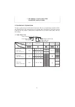
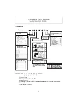
(2) Special Parts
The example hose, P 2 06 AB 075 W stands for :
2 3
4 5
6
7
2 Material : Plastic
3 Working pressure : 17.2 to 20.6 MPa
4 Nominal dia. : 3 / 8"
5 Fitting type : Taper pipe thread R (PT) and straight pipe thread G (PF) with male 30 degrees seat.
6 Length : 75 cm
7 Hose protector : Coil spring
Description ..................... Hose
P 2
06
AB
075
W
1 Part name
3 Recommended
working pressure (MPa)
Over 20.6 .................
............
.... 1
17.2 to 20.6
..........................
..... 2
13.7 to 17.
2
.........................
..... 3
10.8 to 13.7
.........................
..... 4
6.9 to 10.8 .......
.......................
.. 5
2.9 to 6.9 .......
.....................
...... 6
1.5 to 2.9 .....
.....................
........ 7
Below 1.5 ............
..........
........... 8
4 Nominal dia. (inch)
1 / 8" ......................... 02
3 / 16" ....................... 03
1 / 4" ......................... 04
3 / 8" ......................... 06
1 / 2" ......................... 08
5 / 8" ......................... 10
3 / 4" ......................... 12
1" .............................. 16
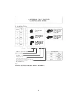
5 Combination of fitting
Fitting type
Code
Taper pipe
thread R (PT)
A
Straight pipe
thread G (PF)
with male 30
degrees seat
B
90 degrees
bent type.
Straight pipe
thread G (PF)
with male 30
degrees seat
C
Without fitting
Y
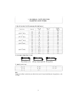
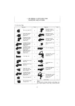
*For the combination of fitting,
refer to the list on the following
page.
6 Total length
(Unit : cm)
Symbol
G (PF)
R (PT)
Rc (PT)
Name
Straight pipe thread
Male taper pipe thread
Female taper pipe thread
List of pipe threads
1
2
8
7
6
5
4
3
2 Hose material
Rubber hose ........... G
Wear-resistant high
pressure rubber
hose ....................... H
Plastic hose ............ P
Wear-resistant
plastic hose ............ F
8 Other accessories
No accessories...Blank
O-ring ....................... 1
7 Hose protector
Coil spring ............... W
Coil tube .................. S
Wire braid ................ B
Tube (Rubber) ......... R
Tube (Vinyl) ............. V
Sponge rubber ......... P
Hose cover ............... K
No protection ..... Blank
90°
30°
G(PF)
R(PT)
30°
G(PF)
Summary of Contents for ViO12-2A
Page 1: ...SERVICE MANUAL EXCAVATOR ViO12 2A...
Page 2: ......
Page 3: ......
Page 9: ......
Page 21: ......
Page 23: ......
Page 37: ......
Page 55: ......
Page 57: ......
Page 99: ......
Page 109: ...5 3 1 5 ELECTRIC SYSTEM 5 3 Wiring Diagram...
Page 114: ......
Page 117: ...6 HYDRAULIC SYSTEM 6 1 3...
Page 118: ...6 HYDRAULIC SYSTEM 6 1 4...
Page 119: ...6 HYDRAULIC SYSTEM 6 1 5 This Page Intentionally Left Blank...
Page 121: ...6 HYDRAULIC SYSTEM 6 1 7...
Page 122: ...6 HYDRAULIC SYSTEM 6 1 8...
Page 123: ...6 HYDRAULIC SYSTEM 6 2 1 6 2 Hydraulic Circuit Schematic...
Page 125: ...6 HYDRAULIC SYSTEM 6 3 2...
Page 126: ...6 HYDRAULIC SYSTEM 6 3 3...
Page 127: ...6 HYDRAULIC SYSTEM 6 3 4 This Page Intentionally Left Blank...
Page 129: ...6 HYDRAULIC SYSTEM 6 3 6...
Page 130: ...6 HYDRAULIC SYSTEM 6 3 7...
Page 131: ...6 HYDRAULIC SYSTEM 6 3 8 This Page Intentionally Left Blank...
Page 133: ...6 HYDRAULIC SYSTEM 6 3 10...
Page 134: ...6 HYDRAULIC SYSTEM 6 3 11...
Page 135: ...6 HYDRAULIC SYSTEM 6 3 12 This Page Intentionally Left Blank...
Page 137: ...6 HYDRAULIC SYSTEM 6 3 14...
Page 138: ...6 HYDRAULIC SYSTEM 6 3 15...
Page 139: ...6 HYDRAULIC SYSTEM 6 3 16 This Page Intentionally Left Blank...
Page 141: ...6 HYDRAULIC SYSTEM 6 3 18...
Page 143: ...6 HYDRAULIC SYSTEM 6 3 20 This Page Intentionally Left Blank...
Page 145: ...6 HYDRAULIC SYSTEM 6 3 22...
Page 147: ...6 HYDRAULIC SYSTEM 6 3 24 This Page Intentionally Left Blank...
Page 149: ...6 HYDRAULIC SYSTEM 6 3 26...
Page 150: ...6 HYDRAULIC SYSTEM 6 3 27...
Page 151: ...6 HYDRAULIC SYSTEM 6 3 28 This Page Intentionally Left Blank...
Page 153: ...6 HYDRAULIC SYSTEM 6 3 30...
Page 155: ...6 HYDRAULIC SYSTEM 6 3 32 This Page Intentionally Left Blank...
Page 157: ...6 HYDRAULIC SYSTEM 6 3 34...
Page 159: ...6 HYDRAULIC SYSTEM 6 3 36 This Page Intentionally Left Blank...
Page 161: ...6 HYDRAULIC SYSTEM 6 3 38...
Page 162: ...6 HYDRAULIC SYSTEM 6 3 39...
Page 163: ...6 HYDRAULIC SYSTEM 6 3 40 This Page Intentionally Left Blank...
Page 165: ...6 HYDRAULIC SYSTEM 6 3 42...
Page 166: ...6 HYDRAULIC SYSTEM 6 3 43...
Page 168: ...6 HYDRAULIC SYSTEM 6 3 45...
Page 169: ...6 HYDRAULIC SYSTEM 6 3 46...
Page 219: ...6 HYDRAULIC SYSTEM 6 7 8 1 4 3 8 7 12 10 10 15 a b c Loctite 262 0 30Nm 0 45Nm...
Page 348: ...7 ADJUSTMENT AND REPAIR 7 5 31 6 Control Levers Pilot valves Control valve...
Page 349: ...7 ADJUSTMENT AND REPAIR 7 5 32 7 Upperstructure Implement Bucket cylinder Arm cylinder...
Page 351: ...7 ADJUSTMENT AND REPAIR 7 5 34 9 Undercarriage High speed travel solenoid valve...
Page 359: ......
Page 360: ...CHAPTER 8 PERIODIC INSPECTION AND SERVICING 8 1 List of Periodic Inspection and Servicing 8 1...
Page 361: ......
Page 364: ...CHAPTER 9 FUEL LUBE OIL AND GREASE RECOMMENDED 9 Fuel Lube Oil and Grease Recommended 9 1...
Page 365: ......
Page 367: ......
Page 369: ......
Page 406: ...CHAPTER 11 REFERENCE DATA 11 1 Specifications for Attachment 11 1...
Page 407: ......

