


6
. HYDRAULIC SYSTEM
6-
1-
6
6
-1-1
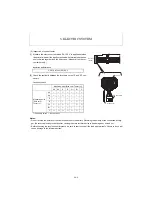
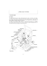
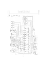
Control Valve Operation
1) Oil Flow from Hydraulic Pump
(1) Oil flow from piston pump P2
The oil from the piston pump P2 flows to the sections
through the port P2 of the inlet section and the parallel
passage.
The travel (L) section is positioned the most upstream in
the control valve, and then the swing, arm and P.T.O.
sections are arranged in that order.
The P.T.O. section is supplied with the oil from both the
piston pumps P1 and P2.
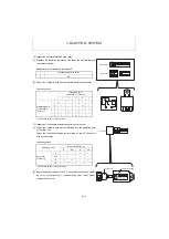
(2) Oil flow from piston pump P1
The oil from the piston pump P1 flows to the sections
through the port P1 of the inlet section and the parallel
passage.
The track gauge change section is positioned the most
upstream in the control valve, and then the boom swing,
boom, bucket, travel (R) and blade sections are
arranged in that order.
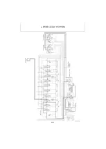
2) Simultaneous Operation of Boom and Bucket
The parallel passage in the bucket section has a throttle
Ø1.4 mm so that the oil can flow to the boom section
more smoothly than to the bucket section even when the
boom is given a heavy load. Therefore, the boom and
the bucket can be operated simultaneously.
3) Simultaneous Operation of Travel and Blade
When the blade is operated while the machine is travel-
ing, the blade cylinder is supplied with the same quantity
of oil from the piston pumps P1 and P2 each through the
throttles in the parallel passage. Therefore, the blade
can be operated while the machine is traveling, with no
travel deviation. However, the travel speed is slowed
down.
Summary of Contents for ViO12-2A
Page 1: ...SERVICE MANUAL EXCAVATOR ViO12 2A...
Page 2: ......
Page 3: ......
Page 9: ......
Page 21: ......
Page 23: ......
Page 37: ......
Page 55: ......
Page 57: ......
Page 99: ......
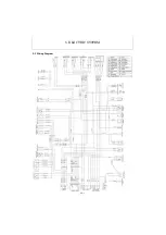
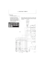
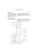
Page 109: ...5 3 1 5 ELECTRIC SYSTEM 5 3 Wiring Diagram...
Page 114: ......
Page 117: ...6 HYDRAULIC SYSTEM 6 1 3...
Page 118: ...6 HYDRAULIC SYSTEM 6 1 4...
Page 119: ...6 HYDRAULIC SYSTEM 6 1 5 This Page Intentionally Left Blank...
Page 121: ...6 HYDRAULIC SYSTEM 6 1 7...
Page 122: ...6 HYDRAULIC SYSTEM 6 1 8...
Page 123: ...6 HYDRAULIC SYSTEM 6 2 1 6 2 Hydraulic Circuit Schematic...
Page 125: ...6 HYDRAULIC SYSTEM 6 3 2...
Page 126: ...6 HYDRAULIC SYSTEM 6 3 3...
Page 127: ...6 HYDRAULIC SYSTEM 6 3 4 This Page Intentionally Left Blank...
Page 129: ...6 HYDRAULIC SYSTEM 6 3 6...
Page 130: ...6 HYDRAULIC SYSTEM 6 3 7...
Page 131: ...6 HYDRAULIC SYSTEM 6 3 8 This Page Intentionally Left Blank...
Page 133: ...6 HYDRAULIC SYSTEM 6 3 10...
Page 134: ...6 HYDRAULIC SYSTEM 6 3 11...
Page 135: ...6 HYDRAULIC SYSTEM 6 3 12 This Page Intentionally Left Blank...
Page 137: ...6 HYDRAULIC SYSTEM 6 3 14...
Page 138: ...6 HYDRAULIC SYSTEM 6 3 15...
Page 139: ...6 HYDRAULIC SYSTEM 6 3 16 This Page Intentionally Left Blank...
Page 141: ...6 HYDRAULIC SYSTEM 6 3 18...
Page 143: ...6 HYDRAULIC SYSTEM 6 3 20 This Page Intentionally Left Blank...
Page 145: ...6 HYDRAULIC SYSTEM 6 3 22...
Page 147: ...6 HYDRAULIC SYSTEM 6 3 24 This Page Intentionally Left Blank...
Page 149: ...6 HYDRAULIC SYSTEM 6 3 26...
Page 150: ...6 HYDRAULIC SYSTEM 6 3 27...
Page 151: ...6 HYDRAULIC SYSTEM 6 3 28 This Page Intentionally Left Blank...
Page 153: ...6 HYDRAULIC SYSTEM 6 3 30...
Page 155: ...6 HYDRAULIC SYSTEM 6 3 32 This Page Intentionally Left Blank...
Page 157: ...6 HYDRAULIC SYSTEM 6 3 34...
Page 159: ...6 HYDRAULIC SYSTEM 6 3 36 This Page Intentionally Left Blank...
Page 161: ...6 HYDRAULIC SYSTEM 6 3 38...
Page 162: ...6 HYDRAULIC SYSTEM 6 3 39...
Page 163: ...6 HYDRAULIC SYSTEM 6 3 40 This Page Intentionally Left Blank...
Page 165: ...6 HYDRAULIC SYSTEM 6 3 42...
Page 166: ...6 HYDRAULIC SYSTEM 6 3 43...
Page 168: ...6 HYDRAULIC SYSTEM 6 3 45...
Page 169: ...6 HYDRAULIC SYSTEM 6 3 46...
Page 219: ...6 HYDRAULIC SYSTEM 6 7 8 1 4 3 8 7 12 10 10 15 a b c Loctite 262 0 30Nm 0 45Nm...
Page 348: ...7 ADJUSTMENT AND REPAIR 7 5 31 6 Control Levers Pilot valves Control valve...
Page 349: ...7 ADJUSTMENT AND REPAIR 7 5 32 7 Upperstructure Implement Bucket cylinder Arm cylinder...
Page 351: ...7 ADJUSTMENT AND REPAIR 7 5 34 9 Undercarriage High speed travel solenoid valve...
Page 359: ......
Page 360: ...CHAPTER 8 PERIODIC INSPECTION AND SERVICING 8 1 List of Periodic Inspection and Servicing 8 1...
Page 361: ......
Page 364: ...CHAPTER 9 FUEL LUBE OIL AND GREASE RECOMMENDED 9 Fuel Lube Oil and Grease Recommended 9 1...
Page 365: ......
Page 367: ......
Page 369: ......
Page 406: ...CHAPTER 11 REFERENCE DATA 11 1 Specifications for Attachment 11 1...
Page 407: ......


