


ENGINE
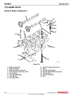
Cylinder Head
5-20
BY Service Manual
© 2009 Yanmar Marine International
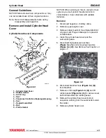
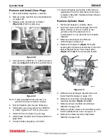
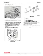
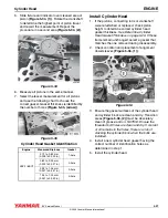
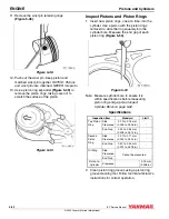
10. Rotate crankshaft using the crankshaft
dampener bolt until No. 1 cylinder is at TDC.
Secure flywheel using flywheel holding tool
OEM No. 11 5 180 (Figure 5-11).
Figure 5-11
Figure 5-11
11. Remove both camshafts. See Remove
12. Remove all hydraulic rocker arm pivots and cam
followers. NOTICE: NEVER mix used valve
train components. When removing any valve
train components, be sure to identify their
original location or store them in an order that
will allow them to be installed in their original
positions.
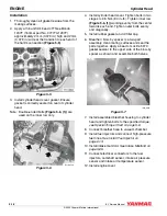
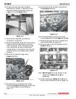
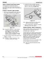
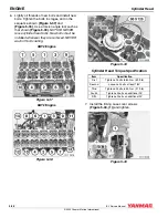
13. Remove oil cooler return pipe screw
Figure 5-12
Figure 5-12
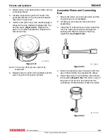
14. Release the locks and disconnect coolant
return pipe (Figure 5-12, (2)). See Disconnect
and Connect Quick-Connect Fittings on
page 7-11.
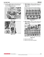
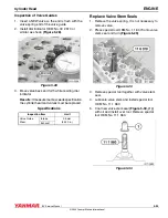
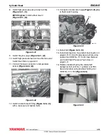
15. Remove three bolts and the coolant branch
Figure 5-13
Figure 5-13
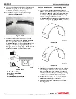
16. Disconnect electrical connector from the
coolant temperature sensor (Figure 5-13, (2)).
17. Remove high-pressure fuel rail. See Remove
and Install Fuel Rail on page 6-20.
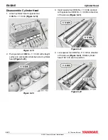
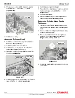
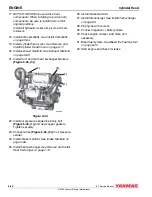
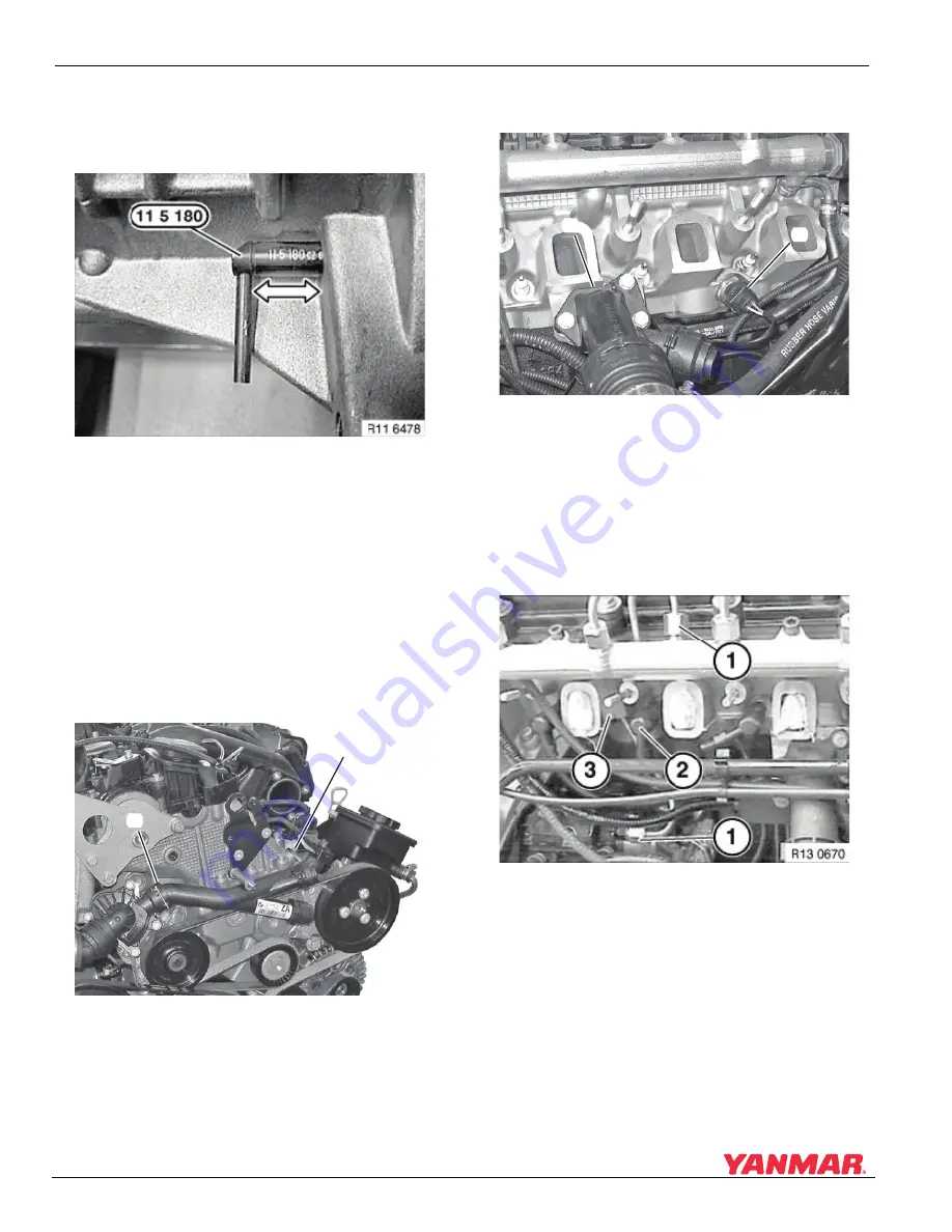
18. Remove pump-to-fuel rail high-pressure line
(Figure 5-14, (1)).
Figure 5-14
Figure 5-14
Note: 4BY2 Engines: Note the position of the
rubber mount (Figure 5-14, (3)) for
reassembly.
19. Remove glow plugs (Figure 5-14, (2)). See
Remove and Install Glow Plugs on page 5-19.
000
3
766
(1)
(2)
000
3
767
(1)
(2)