


ENGINE
Intake Manifold
5-66
BY Service Manual
© 2009 Yanmar Marine International
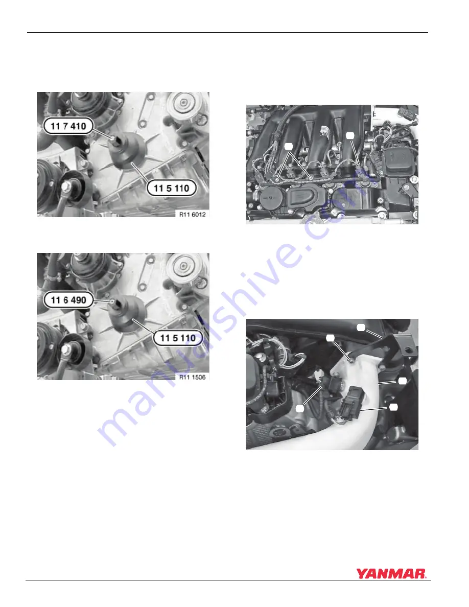
9. Install center screw OEM No. 11 7 410 (4BY2)
or 11 6 490 (6BY2) in end of crankshaft
(Figure 5-125 or Figure 5-126).
Figure 5-125
4BY2 Engines
Figure 5-125
Figure 5-126
6BY2 Engines
Figure 5-126
10. Place seal installer OEM No. 11 5 110 over
center screw and install nut.
11. Tighten nut until seal is flush with timing case
cover. Remove installer tool.
12. Install crankshaft damper. See Remove and
Install Vibration Damper - 4BY2 on page 5-46
and See Remove and Install Vibration
Damper - 6BY2 on page 5-47.
13. Install belts. See Remove and Install Alternator
on page 11-5 and Replace Seawater Pump Belt
on page 7-19.
INTAKE MANIFOLD
Remove
1. Remove injector harness connectors
(Figure 5-127, (1)) from all fuel injectors.
Figure 5-127
Figure 5-127
2. Remove screws (Figure 5-127, (2)) and move
injector harness out of the way.
3. Disconnect electrical connectors from charge
air pressure sensor (Figure 5-128, (1)) and
charge air temperature sensor
(Figure 5-128, (2)).
Figure 5-128
Figure 5-128
4. Remove four screws (Figure 5-128, (3)).
Disconnect charge air pipe (Figure 5-128, (4))
and bracket (Figure 5-128, (5)).
000
3
7
8
0
(2)
(1)
000
3
7
8
1
(1)
(4)
(5)
(
3
)
(2)