GENERAL SERVICE INFORMATION
4-8
3TNV88F Service Manual
Main Electronic Control Components and Features
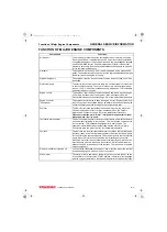
MAIN ELECTRONIC CONTROL COMPONENTS AND FEATURES
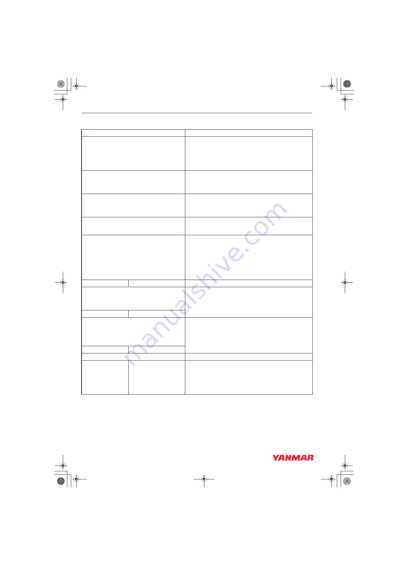
Component/feature
Description
Engine controller (E-ECU)
Adjusts the rack position of the fuel injection pump depending
on the speed command signal from the accelerator sensor, thus
regulating the engine speed and power. The engine controller
also regulates the opening of the EGR valve depending on the
engine speed and power. It serves as the master station for the
following components/control features.
Electronic governor (Eco-governor)
Consists of the engine speed sensor, rack actuator, etc., and is
directly connected to the fuel injection pump in order to regulate
the rack position of the fuel injection pump depending on the
signals communicated with the E-ECU.
Fuel injection pump (for Eco-governor)
Is of single plunger type and equipped with a CSD solenoid
valve that allows the fuel injection timing to advance and the
injection quantity to increase, thereby improving the cold start
performance of the engine.
EGR valve
Controls the exhaust gas recirculation flow rate depending on
the engine speed/load signals from the E-ECU. It is installed on
the top of the exhaust manifold.
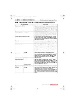
Accelerator sensor
Unlike mechanical governors, the Eco-governor has no
governor lever. The accelerator sensor serves as the governor
lever to provide the speed command signal (voltage signal) to
the E-ECU for engine speed control. It is installed in the
operator cabin of the driven machine. Constant speed engines
for e.g. generator use do not require accelerator sensors
because the engine speed can be shifted via a switch on the
operator's console.
Optional
CAN communication capability is available as an option.
Fault indicator
Is installed on the operator’s console. If a fault occurs in the E-
ECU or Eco-governor, the fault indicator flashes alerting the
operator to a fault. The number of flashes and/or the flashing
pattern vary depending on the type or source of the fault,
enabling quick-fix.
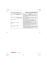
Optional
Engine diagnosis tool
Allows the operator to troubleshoot the cause of a problem
based on detailed information regarding the problem occurring
in the E-ECU or Eco-governor. This tool can also be used for
data maintenance tasks including programming and mapping.
See Failure Diagnosis on page 14-1
.
Option for service
Engine coolant temperature sensor
Allows the CSD to be controlled in engine cold-start conditions.
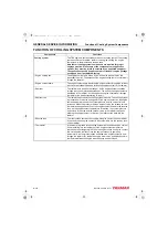
Glow plugs
Optional
When the key switch is turned to the ON position, the glow plugs
are energized for up to 15 seconds. The duration of
energization depends on the engine coolant temperature. The
HEAT indicator is on during energization. When the indicator
goes out, turn the key switch to the START position to start the
engine.
3TNV88F_SVM_A4.book 8 ページ 2012年7月26日 木曜日 午後6時4分

