FUEL SYSTEM
3TNV88F Service Manual
7-13
Fuel Injection Pump
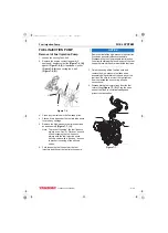
14. To position the fuel injection pump for easier
removal and installation, install a dial indicator
(see Checking and Adjusting Fuel Injection
Timing on page 7-20)
into the injection pump
plunger opening. Using a wrench on the
crankshaft pulley bolt, rotate the crankshaft until
the dial indicator shows that injection pump
plunger is at the bottom of it’s stroke.
15. To aid in reassembly, make reference marks on
the fuel injection pump drive gear, and on either
the gear case cover or idler gear.
NOTICE
After marking the position of the pump drive gear,
do not rotate the engine crankshaft. Rotating the
crankshaft will cause the fuel injection pump to
become misaligned.
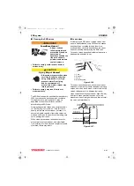
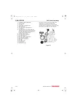
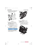
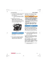
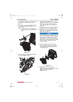
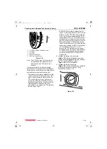
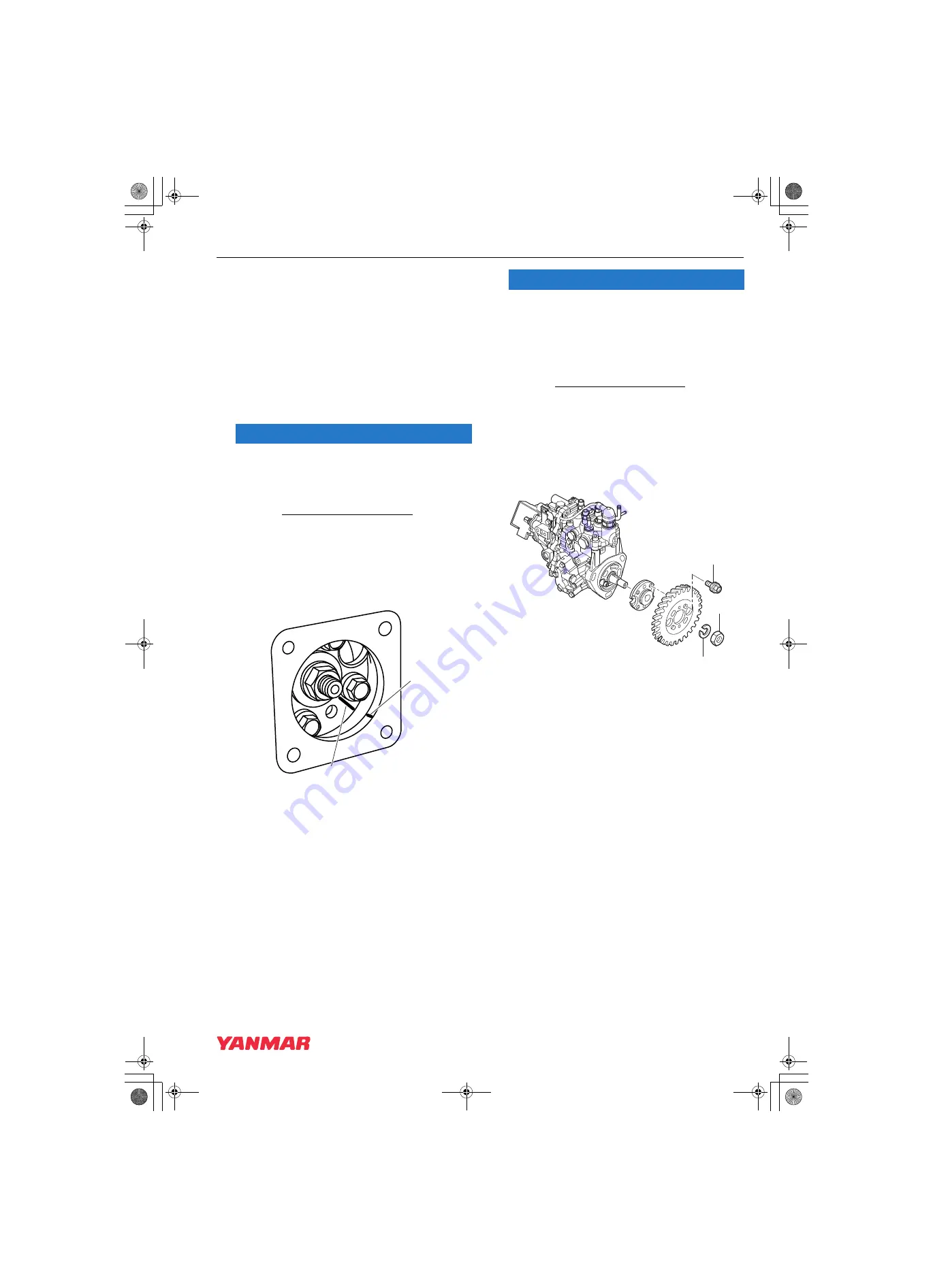
• On 3TNV88F engine the idler gear is not
visible. Make a reference mark on the fuel
injection pump drive gear
(Figure 7-11, (1))
and a matching mark on the bore of the gear
case opening
(Figure 7-11, (2))
.
Figure 7-11
NOTICE
Do not loosen or remove the four bolts retaining
the fuel injection pump drive gear to the fuel
injection pump hub. Do not disassemble the fuel
injection pump drive gear from the hub. Correct
fuel injection timing will be very difficult or
impossible to achieve.
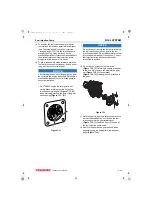
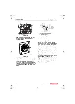
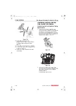
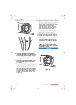
16. Do not loosen or remove the four bolts
(Figure 7-12, (3))
retaining the pump drive gear
to the hub. Only remove the single drive gear
nut
and washer
(Figure 7-12, (2))
, leaving the hub attached to
the gear.
Figure 7-12
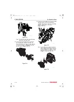
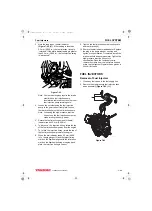
17. Hold the gear train using a large socket wrench
on the crankshaft pulley nut. Loosen the fuel
injection pump drive gear retaining nut
(Figure 7-12, (1))
and turn it out to the end of
the fuel injection pump shaft.
18. Remove the pump drive gear and hub as an
assembly using an appropriate two-bolt gear
puller
2
1
K0000575A
1
2
3
046363-00X01
3TNV88F_SVM_A4.book 13 ページ 2012年7月26日 木曜日 午後6時4分

