background image

5

Ⅲ. INSTALLATION

Before  using  this  instrument,  make  sure  if  it  is  the  type  that  you  requested  and  meets  the  demand  of  the 
environment, pressure and piping conditions where it is used, by specifi cation.

1. Caution of service condition

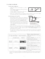
a)  Do  not  use  the  instrument  in  a  place  subjected  to  direct  sunlight,  vibration  or  shock,  or  excessive 

moisture. In particular, vibration and shock to the instrument should shorten its life.

b) Use under the medium and ambient temperature from - 10 to + 50 ℃ .

c)  The instrument is not waterproof. Do not use it in a place subjected to rain, or other splashing water.

d)  The  instrument  cannot  be  installed  outdoors  without  an  appropriate  protection.  If  outdoor  installing  is 

required, the instrument should be housed in a box of drip-proof type for outdoor use.

e) In installing the instrument, select the place where the ground is smooth and fl at.

2. Installation of MS65, MS65F

Panel cut size

3. Pressure of measurement and connection of piping

a)  Measurement of positive pressure

Connect the tube to the high pressure side piping connector (indicated by red color or letter H). The 
lower pressure port (blue or L) should opened to atmosphere, but do not remove the piping connector.

b)  Measurement of negative pressure

Connect the tube to the low pressure side piping connector (blue or L). The high pressure port (red or H) 
should be opened to atmosphere, but do not remove the piping connector.

c)  Measurement of differential pressure

Connect the tube from the high pressure piping connector to the high pressure port (red or H) and from 
the low pressure piping connector to the low pressure port (blue or L).

4. Connectors and piping material

a) Connectors for vinyl or plastic tube (VT, VL, VK connectors)

These are connectors for vinyl, plastic or rubber tubes. Be sure to use I.D. 6 and thickness of 1 mm or 
more. However, the vinyl or plastic tube (2 or more wall thickness) with enough withstanding pressure 
(including vacuum pressure) is required when the instrument range or the line pressure is higher more 
than 50 kPa.

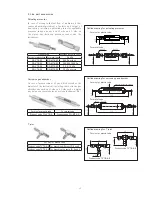
b)  Connectors for metal tube (MT, ML, MK connectors)

These piping connectors can be connected to metal
tube made from copper and aluminum and so on.
(O.D. 6, tolerannce ± 0.1, ring joint type)
When this connector is connected to hard plastic
tube (O.D. 6, I.D. 4), remove the sleeve made of
bress and use the resinous inner sleeve set (XIN6 ×
4) that is the optional accessory.

MS65

MS65F

!

Caution

Tighten the piping 
connectors with the torque 
of 1 N・m.
Do not apply excessive 
torque more than 
necessary, otherwise it 
will damage the instrument 
body.

Inner sleeve set 

for plastic tube

Product code XIN6X4

ᵧᶌᶌᶃᶐίᶐᶃᶑᶇᶌᵇ

ᵱᶊᶃᶃᶔᶃίᶐᶃᶑᶇᶌᵇ

ᵮᶊᵿᶑᶒᶇᶁᴾᶒᶓᶀᶃ

ᵔᵑᶠᵎᵌᵑ

ᵔᵑᶠᵎᵌᵑ

ᵒᶣ᷑ᵓᴾᶆᶍᶊᶃᶑᴾᶍᶐ

ᵒᶣᵫᵒᴾᶆᶍᶊᶃᶑᴾᶒᵿᶎᶎᶃᶂ

ᵗᵒᶠᵎᵌᵑ

ᵓᵎᶠᵎᵌᵑ

ᵑᶣ᷑ᵔᴾᶆᶍᶊᶃᶑᴾᶍᶐ

ᵑᶣᵫᵓᴾᶆᶍᶊᶃᶑᴾᶒᵿᶎᶎᶃᶂ

Summary of Contents for MS65

Page 1: ... U C T I O N M A N U A L 653 0031 1 2 3 Nishi shiriike cho Nagata ku Kobe Japan TEL 078 631 6000 FAX 078 631 6020 READ THE INSTRUCTION MANUAL MANOSTAR SWITCH MS65 MS65F WITH AIR FILTER TR MS65 E09 RoHS Compliant ...

Page 2: ...Caution of piping 6 7 Installation position 6 Ⅳ SETTING OF PRESSURE 1 Switch contact configuration 7 2 Setting of upper limit lower limit 7 3 Reset time 8 Ⅴ ABOUT BUILT IN MICRO SWITCH 1 Material of contact 8 2 Contact material and applicable mecanism for low voltage and low current circuit 8 3 Protection of contact of switch 9 4 About measured gas and contact failure 10 Ⅵ ACCESSORIES 1 Accessory f...

Page 3: ... instrument The instrument is measurable for air and non corrosive gas only The machine is exclusive use of dry air 90 RH or less Using measuring the water or oil it may be damaged and causes the accident Avoid using where the instrument is subject to many vibration and impact Using the instrument where intensified vibration and impact may be damaged the instrument It is expected that gas leaks of ...

Page 4: ... Pa 1 2E 0 2 1 2 0 030 kPa 0 120 kPa 3E 0 5 3 0 080 kPa 0 400 kPa 6E 1 6 0 15 kPa 0 60 kPa Silicone rubber 12E 2 12 0 30 kPa 1 20 kPa 30E 5 30 0 75 kPa 4 00 kPa Out of standard 㹋㹑㸴㸳 㹄 㹆 㹔㹊 㸱㸮㸮 㹂 㸫㹉 㸫㹉 㹂 䠬䠽 㹃 䡇䠬䠽 㹆 㹊 㹔 㹋 㹋㹊 㹔㹊 㻲㼛㼞㻌㼓㼑㼚㼑㼞㼍㼘㻌㼑㼘㼑㼏㼠㼞㼕㼏㼍㼘㻌㼘㼛㼍㼐 㻲㼛㼞㻌㼘㼛㼣㻌㼑㼘㼑㼏㼠㼞㼕㼏㼍㼘㻌㼘㼛㼍㼐 㼂㼀㻌㼟㼠㼞㼍㼕㼓㼔㼠㻌㼠㼥㼜㼑㻌 㼂䠨㻌㼞㼛㼠㼍㼞㼥㻌㼘㼛㼛㼟㼑㻌㼠㼥㼜㼑 㻹㼀㻌㼠㼟㼠㼞㼍㼕㼓㼔㼠㻌㼠㼥㼜㼑 㻹䠨㻌㼞㼛㼠㼍㼞㼥㻌㼘㼛㼛㼟㼑㻌㼠㼥㼜㼑 㻲㼛㼞㻌㼡㼜㼜㼑㼞㻌㼘㼕㼙㼕㼠㻌㼟㼑㼠㼠㼕㼚㼓 㻲㼛㼞㻌㼘㼛㼣㼑㼞㻌㼘㼕㼙㼕㼠㻌㼟㼑㼠㼠...

Page 5: ...de 10 10 to 50 Hz Acceleration 39 m s2 each two hours on triaxial directions 100 m s2 each six times on triaxial direction Between each terminal and case 20 MΩ or more 500 V DC megger Between each terminal and case 1500 V AC 50 60 Hz for one minute Phenol resin and aluminum die cast 1 Vinyl plastic or rubber tube I D 6 Piping applicable model attached with connector for vinyl or plastic tube 2 Met...

Page 6: ...ectrical load type The general electrical load type is decreased contact reliability refer to p 8 The withstanding pressure of the pressure receiving element means The max pressure under which the diaphragm withstands distortion or breakage withstand single pressure The single pressure acting on either H or L side The withstanding pressure of the instrument body means The max pressure under which ...

Page 7: ...de piping connector blue or L The high pressure port red or H should be opened to atmosphere but do not remove the piping connector c Measurement of differential pressure Connect the tube from the high pressure piping connector to the high pressure port red or H and from the low pressure piping connector to the low pressure port blue or L 4 Connectors and piping material a Connectors for vinyl or ...

Page 8: ...nnect it with the pressure receiving instrument through a metal tube which is long enough to cool down the high temperature gas d Errors caused by long distance piping The speed of response is delayed when the product is used for remote monitoring In such application the I D of the connection tube should be as large as possible The time constant is almost inversely proportional to the inner cross ...

Page 9: ...e Be careful about the difference between the upper and lower limit setting switched and also understand the relation between the pressure increase decrease and the contact composition before designing the operational sequence Depending on the purpose of use choose the instrument either upper limit setting type or lower limit setting type Difference of contact movement between upper limit setting ...

Page 10: ... small rivet contact point 2 Contact material and applicable mecanism for low voltage and low current circuit The schematic diagram in the right explains the proper range of load voltage and current for which silver or gold alloy contact is generally used when the contact is used for opening or closing the low voltage and low current circuit with a micro switch When referring to the diagram keep t...

Page 11: ...iode and avoid to apply high voltage to inbetween the contacts This method makes the return time of inductive load slower Choose the diode rated current is more than load current and counter withstand voltage more than 10 times of power supply voltage Diode Zener diode method Diode method proves to be effective when the return time takes too long for inductive load such as relay When you choose ze...

Page 12: ...ic acid and it may also cause electrical contact failure or malfunction of switches b Silicone gas If the gas to be measured contains silicon produced from silicon contained in oil grease filling agent and so on the gas produced by arc generates by opening closing the contact accumulates on the contact surface and causes contact failure Take corrective measures such as the removal of the gas sourc...

Page 13: ...again to fix Replacement of air filter In case of using model with air filter MS65F depending on amount of work conduct disassembly and clean out once in 2 years periodically and replace filters and packings with new ones Filters are constructed as shown in Fig 1 How to change 1 Loosen and take out four assembly screws a from the instrument body and disassemble filter unit 2 Remove the used filters and ...

Page 14: ...G VT6 S Product code FG MT6 S T joint For vinyl or plastic tube Product code TVT6 4 6 For branching different I D 6 and 4 Product code TVT6 6 6 For branching the same I D 6 and 6 Product code Applicable range max value For vinyl or plastic tube For metal tube Pa kPa RS VT6 02 RS MT6 02 200 Pa or less RS VT6 03 RS MT6 03 300 500 1000 Pa RS VT6 04 RS MT6 04 2 3 5 10 kPa RS VT6 06 RS MT6 06 20 kPa or...

Page 15: ...talog specifications or manual Handling or usage of the product other than as described in our product catalog specifications or manual 2 Breakdown due to a reason other than a fault within our product 3 Any product that has been modified or repaired by a party other than us 4 Any breakdown due to a reason that was not foreseeable based on scientific and technical standards applied at the time of ship...

Reviews: