4
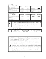
Contact rating :
[For general electrical load]
Specifi cations
Rated voltage
Resistive loads
Inductive loads
Loads on motor
Contact composition
SPDT (single pole double throw type)
Electrical life
100,000 switching cycles
Contact Material
Silver (round rivets point)
30 V DC
3 A
2A
( )
125 V AC
250 V AC
5 A
5 A
3 A
3 A
( )
1 A
0.5 A
[For low electrical load]
Specifi cations
Rated voltage
Resistive loads
Inductive loads
Loads on motor
Contact composition
SPDT (single pole double throw type)
Electrical life
100,000 switching cycles
Contact Material
Gold alloy (cross point)
30 V DC
0.1 A
125 V AC
0.1 A
Characteristics of built-in air fi lter (MS65F)
Material
Polyvinyl pholmor
porous sheet (t = 2 ㎜ )
Average collection rate
97.1 % (ratio in terms of weight)
Retaining capacity
300 g/m
2
time
constant
7ms
power
factor
0.4
!
Caution
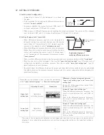
・ In case of driving an inductive load such as relay, contact trouble may be happened due to
counter electromotive force and rush current, therefore insert the protective circuit for
absorbing surge by using diode or varistor. (refer to p. 9)
・ In case of low current or voltage, use the low electrical load type. The general electrical load
type is decreased contact reliability. (refer to p. 8)
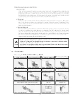
“The withstanding pressure of the pressure receiving element” means ;
The max. pressure under which the diaphragm withstands distortion or breakage (withstand single
pressure) The single pressure acting on either H or L side.
“The withstanding pressure of the instrument body” means ;
The max. pressure under which the instrument body withstand safely without breakage (double side
withstanding pressure) The pressure acing on both high and low sides.
Note :
The withstanding pressure of the instrument body is not the pressure under which the
airtightness of the instrument is guaranteed.
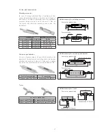
Caution
If the pressure exceeding the withstanding pressure of the pressure receiving element is applied to
both L and H sides at the same time, the imbalance of the ultimate pressure arising from the difference
in the capacity between the L side and H side chambers or tube. It may cause the pressure exceeding
the withstanding pressure and the breakage or distortion of the diaphragm.
When applying the pressure exceeding the withstanding pressure of the diaphragm from both H and L
sides at the same time, increase the pressure slowly and gradually. Likewise, in relieving the pressure,
decrease the pressure slowly.
!


