11
3
2
1
b
1
a
4
a
4
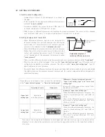
No.
N a m e
①
O-ring
②
Adaptor of level difference connector
③
O-ring
④
Rotary connector
No.
N a m e
①
Packing
②
Filter
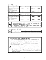
Fig.1
Fig.2
Installation of rotary connector
・ When you change piping connector from straight type to
rotary loose or rotary lock type, refer to the assembly drawing
on the right.
1. After cleaning well around connector area, take off the
straight type connector by the spanner. Because of
preventing intrusion of dust in internal instrument at the
time taking off.
2. The O-ring ① of the assembly drawing has been installed
already on the instrument body.
The O-ring ③ has been installed on the adaptor of level
difference connector ② .
3. Install the adaptor of level difference connector to
mainbody to tighten the part Ⓑ by the spanner in advance.
Then tighten ground Ⓐ of level difference connector by
spanner. Install the rotary connector to both instrument
body and the level difference adaptor.
4. After installing, make sure that connector part is turned.
In case of lock type, make sure that connector part is not
turned.
However, in piping, loose the head and move the
connector where it is desired to be located and should be
tightened again to fi x.
Replacement of air fi lter
・ In case of using model with air fi lter (MS65F), depending on
amount of work, conduct disassembly and clean out once in
2 years periodically and replace fi lters and packings with new
ones.
・ Filters are constructed as shown in Fig.1.
<How to change>
1. Loosen and take out four assembly screws
a
from the
instrument body, and disassemble fi lter unit.
2. Remove the used fi lters ② and packings ① from case
b
,
and clean out the inner surfaces of case
b
and
c
.
3. Replace new packings and filters with refer to Fig.2.
Packings should be fi t correctly into the grooves on both
side of case
b
.
Next, place new fi lters onto both sides of case
b
. (There
are no distinction between the front and the back in
packing and fi lter either.)
4. Then put case
b
on top of case
c
together as to coincide the position of the
through-hole on case
b
with the air hole
on case
c
correctly. (refer to Fig.2)
5. Place the instrument body on top of case
b
piled with case
c
.
Make sure that the relation of position
between the installing leg of case
c
and
the connectors on the instrument body
are the same as that Fig.2 shows. And
also make sure that convex parts under
the instrument body are fi t into the hollow
parts (spot facings) on each corner of case
b
.
6. Insert four assembly screws
a
into screw-
holes as shown in Fig.1 and tighten the
instrument body and cases
b
c
fi rmly.


