background image

56 

En

Using iPod™

y

• For a complete list of status messages that appear in the front panel display and in the OSD, see the “iPod” section in 

“Troubleshooting” on page 106.

• While your iPod is stationed in the Yamaha iPod universal dock connected to the DOCK terminal of this unit, your iPod battery is 

automatically charged as long as this unit is turned on.

Controlling iPod in the Simple Remote 
mode

You can perform some basic operations such as play, 
pause, stop, backward/forward search, and track skip 
using the remote control without the aid of the OSD. Such 
basic operations can be performed also on your iPod. 

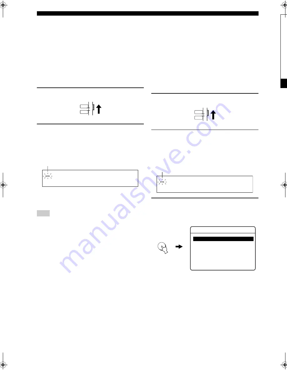
1

Set the operation mode selector to TV/AV.

2

Press AUX3/DOCK and set your iPod in the 
Yamaha iPod universal dock. 

In the front panel display, “iPod connected” appears 
and the DOCK indicator lights up.

y

Use 

#

 and 

*

 on the remote control interchangeably to toggle 

between play and pause operations.

Information on the current song appears only in the iPod screen 
but not in the front panel display of this unit. 

Controlling iPod in the Menu Browse 
mode

You can perform the advanced operations using the remote 
control with the aid of the OSD. In the OSD, you can 
browse the song list stored on your iPod. Further, you can 
change or adjust the settings on your iPod as desired. Such 
advanced operations cannot be performed on your iPod.

1

Set the operation mode selector to TV/AV.

2

Press AUX3/DOCK and set your iPod in the 
Yamaha iPod universal dock. 

In the front panel display, “iPod connected” appears 
and the DOCK indicator lights up.

3

Press DISPLAY, and display the menu 
browse mode.

The OSD appears on your TV.

Note

YSP

TV/AV

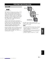
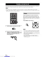
i P o d c o n n e c t e d

Lights up

YSP

TV/AV

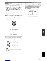
i P o d c o n n e c t e d

Lights up

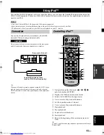
DISPLAY

>

>
>
>
>
>
>

Playlists 

Artists
Albums
Songs
Genres
Composers
Settings

iPod

Top

01EN_YSP-30D_B.book  Page 56  Monday, October 29, 2007  10:31 AM

Black process 45.0° 240.0 LPI 

Summary of Contents for YSP-30D

Page 1: ...YSP 30D YSP 30D Digital Sound ProjectorTM B ...

Page 2: ... vacation disconnect the power supply cable from the wall outlet 16 Be sure to read the Troubleshooting section on common operating errors before concluding that this unit is faulty 17 Before moving this unit press STANDBY ON to set this unit in standby mode and disconnect the power supply cable from the wall outlet 18 Condensation will form when the surrounding temperature changes suddenly Discon...

Page 3: ...MEMORY 48 DAB service information 50 Accessing DAB MENU 51 INIT SCAN 51 TUNE AID 52 DRC MODE 53 PRUNE LIST 54 PRESET DELETE 54 Using iPod 55 Connection 55 Controlling iPod 55 Enjoying surround sound 58 5 Beam 58 Stereo plus 3 Beam 59 3 Beam 59 My Surround 59 Enjoying 2 channel sources in surround sound 61 Enjoying TV in surround sound 62 Adjusting surround mode parameters 63 Enjoying stereo sound ...

Page 4: ...rs and 21 full range small speakers You can fine tune the parameters of this unit to adjust the delay time for separate sound beams resulting in highly directional sound that comes in on the listening position from all directions The YSP 30D projects sound beams containing surround sound information for the front right R front left L surround right SR and surround left SL speaker positions which a...

Page 5: ...h the aid of the supplied IntelliBeam microphone You can avoid troublesome listening based speaker setup and achieve highly accurate sound beam adjustments that best match your listening environment Compatibility with the Newest Technologies This unit employs decoders compatible with Dolby Digital DTS Dolby Pro Logic Dolby Pro Logic II DTS Neo 6 and Music Enhancer Dolby Digital This is the standar...

Page 6: ...igh Definition Multimedia Interface are trademarks or registered trademarks of HDMI Licensing LLC Manufactured under license from 1 Ltd Worldwide patents applied for The logo and Digital Sound Projector are trademarks of 1 Ltd TruBass SRS and the symbol are registered trademarks of SRS Labs Inc TruBass technology is incorporated under license from SRS Labs Inc is a trademark of DiMAGIC Co Ltd iPod...

Page 7: ...ween the manual and the product the product has priority 1 Install this unit in your listening room See Installation on page 13 2 Connect this unit to your TV and other external components See Connections on page 16 3 Prepare the remote control and turn on the power of this unit See Getting started on page 27 4 Run AUTO SETUP See AUTO SETUP IntelliBeam on page 32 5 Play back a source See Playback ...

Page 8: ...ST 3BEAM 3BEAM MUSIC MOVIE VOL MODE AUTO SETUP MACRO TV INPUT1 YSP TV AV CH ENTRY 4 6 3 2 1 AUX1 AUX2 DAB STB TV DVD AUX3 TV POWER POWER STANDBY ON DOCK 10 0 7 8 9 5 AV Remote control 1 Batteries 2 AA R6 UM 3 OSD video pin cable 1 IntelliBeam microphone 1 Fasteners 4 Audio pin cable 1 Digital audio pin cable 1 Optical cable 1 Cable clamp 1 Cardboard microphone stand 1 Orange White Red Yellow Indoo...

Page 9: ...t sources see page 42 Outputs a test tone to experience the sound beam see page 95 6 VOLUME Controls the volume level of all audio channels see page 44 7 STANDBY ON Turns on the power of this unit or sets it to the standby mode see page 28 When you turn on this unit you will hear a click sound followed by the 4 to 5 second interval before sound reproducing In the standby mode this unit consumes a ...

Page 10: ...it via the DOCK terminal on this unit A SRS TruBass indicator Lights up when TruBass is turned on see page 83 B EQUAL indicator Lights up when the TV volume equal mode is selected see page 71 C NIGHT indicator Lights up when one of the night listening enhancers is selected see page 71 D SLEEP indicator Lights up when the sleep timer is set see page 72 E SECONDARY indicator Lights up when this unit...

Page 11: ...jack Connect an external component via an optical digital connection see page 24 9 TV STB OPTICAL DIGITAL INPUT jack Connect your TV digital satellite tuner or cable TV tuner via an optical digital connection see pages 19 and 21 0 DVD COAXIAL DIGITAL INPUT jack Connect your DVD player via a coaxial digital connection see page 20 A AUX 1 HDMI IN jack Connect your digital satellite tuner cable TV tu...

Page 12: ...SP program buttons Select the CINEMA DSP programs see page 67 8 ENHANCER Turns on or off the Music Enhancer see page 70 9 Cursor buttons ENTER Select and adjust SET MENU items 0 DISPLAY Displays information on the selected input signal A VOLUME Increases or decreases the volume level of this unit see page 44 B MUTE Mutes the sound Press again to restore the audio output to the previous volume leve...

Page 13: ...e only when DAB services are preset M SLEEP Sets the sleep timer see page 72 N INPUTMODE Toggles between input modes AUTO DTS and ANALOG see page 91 O Beam mode buttons Change the beam mode settings see pages 58 64 and 65 P SUR DECODE Selects the surround mode for playback see page 61 Q MENU Displays the setup menu on your TV monitor see pages 34 and 77 R Operation mode selector Selects the operat...

Page 14: ... of using the cursor buttons 4 DISPLAY DAB and iPod Displays information when this unit is receiving a DAB service see page 50 or playing back your iPod see page 56 5 MEMORY DAB Stores preset DAB services see page 48 6 MENU DAB Displays the DAB menu on your TV monitor see page 51 7 Operation mode selector Selects the operation mode of this unit Select YSP when operating this unit and select TV AV ...

Page 15: ... when the listening position is not directly facing toward the front of this unit You can also enjoy surround sound by selecting 2 channel or 5 channel stereo playback see page 64 or My Beam see page 65 as the beam mode even if your listening room may not fulfill the above conditions Make sure you leave an adequate amount of ventilation space so that heat can escape Make at least 5 cm 2 in of spac...

Page 16: ...nstall this unit as close to the exact center of the wall as possible Example 2 Install this unit so that the sound beams can be reflected off the walls Example 3 Install this unit as close to the exact front of your normal listening position as possible ...

Page 17: ...ke sure that the rack is large enough to allow adequate ventilation space around this unit see page 13 and that it is strong enough to support the weight of both this unit and your TV Affixing this unit Peel off the film from each of the four supplied fasteners and then secure them to the bottom four corners of this unit and the top of the rack etc Do not install this unit on top of a slanted surf...

Page 18: ...ayer VCR digital satellite tuner cable TV tuner digital air wave tuner portable audio player game console and iPod Further by connecting a subwoofer to this unit you can enjoy reinforced low bass sounds For details on how to connect various types of external components to this unit see pages 18 to 25 Do not connect this unit or other components to the mains power until all connections between comp...

Page 19: ...io signals may not be output depending on the type of DVD player This unit is not compatible with HDCP incompatible HDMI or DVI components y We recommend that you use an HDMI cable shorter than 5 m 16 ft with the HDMI logo printed on it Use a conversion cable HDMI jack DVI D jack to connect this unit to other DVI components Priority order for audio input signals When multiple types of audio signal...

Page 20: ...ONTROL is set to OFF see page 86 and this unit is in the standby mode the signals input at the HDMI IN jacks are not output at the HDMI OUT jack y We recommend that you secure the HDMI cable s with adhesive tape etc once you have connected the HDMI cable s to the HDMI jack s of this unit HDMI cable OSD video pin cable Optical cable Connections using HDMI cables Notes AUX 1 DVD IN OUT HDMI A A A DI...

Page 21: ...he supplied cable clamp see page 17 If you make analog and optical digital audio connections at the same time as shown in the illustration below the digital audio signals input at the TV STB OPTICAL DIGITAL INPUT jack take priority over the analog audio signals input at the TV STB AUDIO INPUT jacks Even if you connect your TV and this unit via the HDMI jack you need to connect the video input jack...

Page 22: ...er recorder is properly set to output Dolby Digital and DTS digital audio signals If not adjust the system settings of your DVD player recorder For details refer to the operation manual supplied with your DVD player recorder If your DVD player recorder does not have a coaxial digital output jack make an optical digital audio connection instead see page 24 Audio pin cable Digital audio pin cable Co...

Page 23: ...plugged affix the optical cable in the supplied cable clamp see page 17 Audio pin cable Optical cable Connecting a digital satellite tuner or a cable TV tuner DIGITAL INPUT OUT TV STB DVD SUBWOOFER TV STB AUX 1 AUX 1 AUX 2 COAXIAL OPTICAL VIDEO DOCK AUDIO INPUT ANTENNA Rear panel of this unit Analog audio output L R Optical digital output Digital satellite tuner or cable TV tuner Video signal to t...

Page 24: ... cable from being unplugged affix the optical cable in the supplied cable clamp see page 17 Audio pin cable Optical cable Connecting a digital airwave tuner DIGITAL INPUT OUT TV STB DVD SUBWOOFER TV STB AUX 1 AUX 1 AUX 2 COAXIAL OPTICAL VIDEO DOCK AUDIO INPUT ANTENNA Digital airwave tuner Connect to the analog audio output jacks on the TV Optical digital output Rear panel of this unit Video signal...

Page 25: ...nalog audio output jack on your portable audio player to the AUX 3 input jack on the front panel of this unit 3 5 mm stereo mini plug cable Connecting a portable audio player AUX 3 Portable audio player Front panel of this unit Analog audio output Audio ...

Page 26: ...e optical cable from being unplugged affix the optical cable in the supplied cable clamp see page 17 If you make analog and digital audio connections at the same time as shown in the illustration below the digital audio signals input at the AUX 1 OPTICAL DIGITAL INPUT or AUX 2 COAXIAL DIGITAL INPUT jack take priority over the analog audio signals input at the AUX 1 AUDIO INPUT jacks Audio pin cabl...

Page 27: ...bwoofer To output sound from the connected subwoofer turn on the power of your subwoofer and then run AUTO SETUP see page 32 or select SWFR for BASS OUT in SUBWOOFER SET see page 82 Subwoofer pin cable Connecting a subwoofer DIGITAL INPUT OUT TV STB DVD SUBWOOFER TV STB AUX 1 AUX 1 AUX 2 COAXIAL OPTICAL VIDEO DOCK AUDIO INPUT ANTENNA 5 Monaural input Subwoofer Rear panel of this unit Audio 5 ...

Page 28: ...nd worldwide DAB frequencies visit WorldDAB online at http www worlddab org The supplied indoor DAB antenna should provide sufficient signal strength However if the DAB signals are weak use a commercially available outdoor DAB antenna for better reception Once all other connections are complete plug the AC power supply cable into the AC wall outlet Connecting the DAB antenna Notes DIGITAL INPUT OU...

Page 29: ...g cases The remote control is left without batteries for more than two minutes Exhausted batteries remain in the remote control The buttons on the remote control are accidentally pressed when you change batteries If the memory stored in the remote control is unwantedly erased insert new batteries and set the remote control codes again y Remove the transparent sheet before using the remote control ...

Page 30: ... the front panel or on the remote control is operational and the other control buttons on the front panel or on the remote control are not operational until the power of this unit is turned on Turning on this unit or setting it to the standby mode STANDBY ON VOLUME INPUT MEMORY SEARCH MACRO TV INPUT1 AUX1 AUX2 DAB STB TV DVD AUX3 TV POWER POWER STANDBY ON DOCK AV STANDBY ON STANDBY ON or Front pan...

Page 31: ...deo input jack on your TV is connected to the VIDEO OUT jack on this unit to display the OSD of this unit 2 Press STANDBY ON to turn on the power of this unit 3 Turn on the power of your TV The following screen appears on your TV If the OSD does not appear use the remote control supplied with your TV to switch the video input until the OSD appears Using SET MENU Displaying the OSD on screen displa...

Page 32: ...SP See Playback on page 42 Enjoying surround sound on page 58 and Using sound field programs on page 67 Run MANUAL SETUP See MANUAL SETUP on page 76 y If you cannot clearly hear a sound beam from a specific channel adjust settings for SETTING PARAMETERS see page 78 or for BEAM ADJUSTMENT see page 79 in BEAM MENU If there are acoustically absorbent objects such as curtains in the path of the sound ...

Page 33: ...s MENU once more You can also perform the following operations while viewing information in the front panel display 3 Press to select LANGUAGE SETUP and press ENTER The following screen appears on your TV 4 Press to select the desired language and press ENTER Choices ENGLISH English DEUTSCH German Français French ESPAÑOL Spanish ITALIANO Italian NEDERLANDS Dutch Русский Russian Changing OSD langua...

Page 34: ...is feature optimizes the beam angle so that the parameter best matches your listening environment Sound optimization This feature optimizes the beam delay volume and quality so that the parameters best match your listening environment This unit performs a series of checks to optimize the beam angle delay volume and quality You can choose to optimize all or part of the parameters 1 The beam angle c...

Page 35: ...walls will be regarded as a protruding part of the walls The best possible results are achieved if the IntelliBeam microphone is placed at the same height as your ears would be when you are seated in your listening position However if this is not possible you can manually fine tune the sound beam angle and balance the sound beam output levels using MANUAL SETUP see page 76 once the AUTO SETUP proc...

Page 36: ...Beam microphone is firmly connected to this unit and properly placed in your listening room follow the procedure below to start the AUTO SETUP procedure You can also enter the AUTO SETUP procedure simply by pressing and holding AUTO SETUP for more than two seconds In this case this unit performs both of the beam optimization and sound optimization procedures IntelliBeam microphone Center line 1 2 ...

Page 37: ...Run SOUND OPTIMZ only You can save the settings optimized by the AUTO SETUP procedure see page 39 A set of settings optimized according to the specific conditions of your listening environment can be recalled later depending on the varying conditions of your listening environment see page 40 1 Press STANDBY ON to turn on the power of this unit If a subwoofer is connected to this unit turn on the p...

Page 38: ...ore using this unit If you have manually set the beam angle This menu takes about two minutes You must optimize the beam angle in the BEAM OPTIMZ only procedure before starting the SOUND OPTIMZ only procedure 6 Check the following points once again before starting the AUTO SETUP procedure Is the IntelliBeam microphone firmly connected to this unit Is the IntelliBeam microphone placed in a proper l...

Page 39: ...wo seconds and then disappears from your TV If ENVIRONMENT CHECK FAILED is displayed in step 8 the following screen is displayed after pressing ENTER In this case see ERROR E 1 in Error messages for AUTO SETUP on page 38 Press ENTER to exit AUTO SETUP and then run the procedure again from step 3 10 Disconnect the IntelliBeam microphone from the INTELLIBEAM MIC jack on the front panel y If you want...

Page 40: ...O SETUP procedure was in progress Make sure that the IntelliBeam microphone is firmly connected to this unit 33 ERROR E 3 Unexpected control is detected Please re try Some other operations were performed on this unit while the AUTO SETUP procedure was in progress Do not perform any other operations while the AUTO SETUP procedure is in progress ERROR E 4 Please check MIC position MIC should be set ...

Page 41: ...ed at the bottom of the screen To return to the previous screen while using SET MENU press RETURN To exit from the SET MENU screen press MENU once more You can also perform the following operations in the front panel display 3 Press to select MEMORY and press ENTER The following screen appears on your TV 4 Press to select SAVE and press ENTER The following screen appears on your TV Using the syste...

Page 42: ...ET MENU screen appears on your TV y The control buttons used for SET MENU are displayed at the bottom of the screen To return to the previous screen while using SET MENU press RETURN To exit from the SET MENU screen press MENU once more You can also perform the following operations in the front panel display 3 Press to select MEMORY and press ENTER The following screen appears on your TV MEMORY1 S...

Page 43: ... parameters saved as MEMORY1 MEMORY2 or MEMORY3 are loaded Once the parameters are loaded the display returns to the SET MENU screen 7 Press MENU to exit The SET MENU screen disappears from your TV ENTER MEMORY1 MEMORY2 MEMORY3 Select ENTER Enter 1 MEMORY LOAD p p ENTER MEMORY1 Load Now Push ENTER to Load 1 MEMORY LOAD ENTER ENTER MEMORY1 Loading 1 MEMORY LOAD ENTER MEMORY AUTO SETUP MANUAL SETUP ...

Page 44: ...ontrol operations y In addition to controlling this unit you can also operate other AV components if you set up the remote control with the appropriate remote control codes and set the operation mode selector to TV AV to change the control area see page 100 Press TV to play back a TV program Press STB to play back a satellite broadcast Press DVD to play back a DVD Playback Selecting the input sour...

Page 45: ... the input source 4 Play back DVD on your DVD player using the supplied remote control Audio signals from your DVD player are output from this unit y You can use the supplied demonstration DVD to check the digital signals being input at the DVD player with the digital connection optical coaxial HDMI The input channel and LFE indicators light up when this unit detects the 5 1 channel signal input a...

Page 46: ...me level indicator flashes 2 Press MUTE again or press VOLUME to resume the sound output AUDIO MUTE OFF appears temporarily in the front panel display or the numeric value of the current volume level appears if you press VOLUME and the volume level indicator lights up The sound output of all input sources including multi channel as well as stereo sources is muted at the same time y You can select ...

Page 47: ...usly in each ensemble This means that you can choose between several radio programs within one frequency In addition to the audio signal service information is also broadcast and displayed in the front panel display of this unit Part of the service information is text data information called DLS Dynamic Label Segment For more information see page 50 With DAB there is no need to remember channel fr...

Page 48: ...bles While the scan is in progress Scanning and the percentage of the progress of the scan appear in the front panel display When this unit completes the scan FINISH and the number of receivable DAB services appear in the front panel display and then this unit enters the DAB tuning mode automatically y When you want to cancel the initial scan in the middle press RETURN If the initial scan operatio...

Page 49: ... on the front panel repeatedly to select DAB as the input source 3 Press SEARCH to switch between the DAB tuning modes When you select PRESET the PRESET indicator lights up in the front panel display y If you press just after selecting a DAB tuning mode you can tune into the top or bottom of the DAB service list 4 Press to select a registered DAB service y Press to move to the top of the DAB servi...

Page 50: ...TY appears You can also choose the assigned preset number In this case the previous service is replaced with the current service y Press to move to the top of the DAB service list 3b Use the numeric buttons to enter a preset number For example to assign 56 to the current DAB service If the number entered already exists i e already assigned to a service then the previous service is replaced with th...

Page 51: ...along with the services appear unassigned preset numbers are skipped 2b Use the numeric buttons to enter a preset service number For example to select the preset DAB service numbered 56 For numbers less than 10 simply press ENTER followed by the number If there is no service assigned to the preset numbers entered the numbers entered followed by EMPTY appears in the front panel display for one seco...

Page 52: ...t or speaker or even what the next song or program will be may be displayed This data is continuously updated by the DAB broadcaster thus it often changes with every new song or program Other data such as news weather and sports headlines may be broadcast as well Ensemble label Displays the name of the current ensemble maximum letters Program type Displays the genre song program type of the curren...

Page 53: ...r area When this operation is selected this unit scans the entire band and creates a registry list of every receivable DAB ensemble and service You must perform this scan during the initial setup of this unit before tuning into any DAB services Selective initial scan 1 Access DAB MENU by following steps 1 through 4 as described in Accessing DAB MENU on this page INIT SCAN appears in the front pane...

Page 54: ...NE AID displays the strength of the DAB signal being received by this unit in the front panel display Use TUNE AID to adjust the positioning of the indoor DAB antenna and this unit and discover which setup has the best reception state It is recommended that you use TUNE AID when setting up this unit in order to maximize DAB reception ability 1 Access DAB MENU by following steps 1 through 4 as desc...

Page 55: ...he front panel display 2 Press twice DRC MODE appears in the front panel display 3 Press ENTER The DRC MODE option appears in the front panel display 4 Press to switch between AUTO and OFF If you select DRC MODE AUTO and the broadcast contains DRC data then the DRC indicator lights up in the front panel display 5 Press ENTER The unit returns to the DRC MODE menu display DRC MODE INIT SCAN DRC MODE...

Page 56: ... to delete specific unnecessary services from the DAB registry list 1 Access DAB MENU by following steps 1 through 4 as described in Accessing DAB MENU on page 51 INIT SCAN appears in the front panel display 2 Press four times PRESET DEL appears in the front panel display 3 Press ENTER DELETE appears in the front panel display 4 Press Select the setting number of the service you wish to remove Onl...

Page 57: ...me time and when the DOCK indicator is lit in the front panel display iPod output takes priority 1 Navigate through the iPod menu and starts playback ENTER 2 Displays the OSD on screen menu menu 3 Selects AUX3 DOCK as the input source 4 Use to return to the previous iPod menu 5 Sets the operation mode of this unit 6 Use to return to the previous iPod menu 7 Stops playback 8 Pauses playback 9 Searc...

Page 58: ...he DOCK indicator lights up y Use and on the remote control interchangeably to toggle between play and pause operations Information on the current song appears only in the iPod screen but not in the front panel display of this unit Controlling iPod in the Menu Browse mode You can perform the advanced operations using the remote control with the aid of the OSD In the OSD you can browse the song lis...

Page 59: ... toggle between the choices Choices Off One All Select Off to deactivate this function Select One for repeated playback of a song Select All for repeated playback of a sequence of songs y Press RETURN or MENU to go back to the previous menu The information on the current song also appears in the front panel display You can set the front panel display mode CONT or ONCE For details see SCROLL Front ...

Page 60: ...urround right channels This mode is ideal for enjoying surround sound effects to the fullest when you watch DVDs recorded in a multi channel format or play back 2 channel sources in a multi channel format Press 5BEAM to select 5 Beam To achieve the best surround sound effect make sure that there are no obstacles placed in the path of sound beams in that the objects may prevent the sound beams from...

Page 61: ...and the surround left and right sound beams cannot be reflected off the wall Press 3BEAM to select 3 Beam y You can achieve a more realistic surround effect if you adjust settings for IMAGE LOCATION in BEAM MENU see page 81 When you play back multi channel sources surround left and right signals are mixed down and output from the front left and right channels The front left and right sound beams a...

Page 62: ...d modes are not available Prohibit appears in the front panel display when you press SUR DECODE The surround modes are available when the beam mode is set to a setting other than the 2 channel or 5 channel stereo playback see page 64 and My Surround see page 59 when the CINEMA DSP programs are turned off see page 69 when the movie program is selected as the CINEMA DSP program see page 68 In this c...

Page 63: ...so turned off see page 70 1 Set the operation mode selector to YSP 2 Press SUR DECODE repeatedly or press SUR DECODE and then press to switch between surround modes Choices Neo 6 Cinema Neo 6 Music PRO LOGIC PLII Movie PLII Music PLII Game Default setting Neo 6 Cinema Enjoying 2 channel sources in surround sound STEREO MY SUR MY BEAM ENHANCER MENU RETURN DISPLAY ENTER SUR DECODE OFF SPORTS 5BEAM S...

Page 64: ... until you can no longer hear any audio being output To reduce the TV volume level use the remote control supplied with your TV 5 Press VOLUME to adjust the volume level 6 Press SUR DECODE repeatedly or press SUR DECODE and then press to switch between surround modes Signals input from 2 channel sources are played back in multi channels For more information on surround modes see page 60 Enjoying T...

Page 65: ... ON OFF Default setting OFF DIMENSION Adjusts the difference in volume between the front and surround channels to the desired volume balance Control range 3 toward the surround direction to 3 toward the front direction Default setting STD standard C WIDTH Distributes the center channel sound to the left and right If 0 is selected the center channel sound is output only from the center channel Cont...

Page 66: ... Press STEREO to select the 2 channel stereo playback as the beam mode STEREO appears in the front panel display When you play back multi channel sources all signals except those from the front left and right channels are mixed down and output from the front left and right channels No audio is output from the center and surround channels Sounds are output from front left and right center and surro...

Page 67: ... unit while the test tones are being output so that the My Beam microphone can collect the test tones Control range L60 to R60 Operation guarantee range 6 m 20 ft L45 to R45 If an error occurs an error buzzer is played and MY BEAM ERROR is displayed in the front panel display An error may occur if the listening room is noisy Make sure that the listening room is as quiet as possible while the test ...

Page 68: ... the auto adjust function 1 Set the operation mode selector to YSP 2 Press MY BEAM MY BEAM is displayed in the front panel display 3 Press while MY BEAM is displayed to adjust the beam angle Control range L90 to R90 Press repeatedly to increase the horizontal angle on the left side Press repeatedly to increase the horizontal angle on the right side Using manual adjust function YSP TV AV 5 MY BEAM ...

Page 69: ...ny environment there are two distinct types of sound reflections combined with the direct sound coming straight to our ears from the player s instrument to make up the sound field Early reflections Reflected sounds reach our ears extremely rapidly 50 ms to 80 ms after the direct sound after reflecting from one surface only from the ceiling or the wall for example Early reflections help add clarity...

Page 70: ...C to select the music CINEMA DSP program Movie program Select this CINEMA DSP program when you play back movie sources especially the ones encoded in Dolby Digital DTS or Dolby Surround This program clearly reproduces dialog and sound effects thus creating a broad and expansive cinematic space amid silence 1 Set the operation mode selector to YSP 2 Press MOVIE to select the movie CINEMA DSP progra...

Page 71: ...ers However you can also adjust the effect level of the CINEMA DSP programs relative to the level of the direct sound so that each CINEMA DSP program can reflect your listening environment and your preference even more accurately 1 Set the operation mode selector to YSP 2 Press MUSIC MOVIE or SPORTS to select the desired CINEMA DSP program 3 Press DSP LEVEL is displayed in the front panel display ...

Page 72: ...s If a CINEMA DSP program is selected while the Music Enhancer is on the Music Enhancer is turned off automatically In this case the Music Enhancer remains off even after the CINEMA DSP program is canceled Likewise if the Music Enhancer is turned on while a CINEMA DSP program is selected the CINEMA DSP program is canceled automatically In this case the CINEMA DSP program remains off even after the...

Page 73: ...USIC when listening to music sources to preserve ease of listening for all sounds Select TV EQUAL VOLUME when watching TV programs Select OFF to turn off the volume mode 3 Press to adjust the effect level of compression while NIGHT CINEMA NIGHT MUSIC or TV EQUAL VOLUME is displayed Select Effect Lvl MIN for minimum compression Select Effect Lvl MID for standard compression Select Effect Lvl MAX fo...

Page 74: ...isplay while switching the interval for the sleep timer Each time you press SLEEP the front panel display changes as shown below 3 Wait for a few seconds without operating this unit to confirm the setting for the sleep timer The SLEEP indicator lights up in the front panel display indicating that the sleep timer is activated Using the sleep timer STEREO MY BEAM MEMORY SEARCH SLEEP INPUTMODE ENHANC...

Page 75: ... confirm the setting for the sleep timer The SLEEP indicator disappears from the front panel display indicating that the sleep timer is deactivated The previous setting for the sleep timer before you deactivate it is stored in the system memory y The sleep timer setting can also be deactivated if you press STANDBY ON to set this unit to the standby mode or unplug the AC power supply cable from the...

Page 76: ...nal is displayed as follows y When the input signal is unclear ___ is displayed for the sampling frequency Displaying the input source information ENHANCER MENU RETURN DISPLAY TV VOL VOLUME MUTE TV INPUT TV MUTE ENTER SUR DECODE OFF CH ENTRY 10 0 7 8 9 YSP TV AV YSP TV AV Input signal Indicator Sampling frequency Dolby digital DOLBY DGTL 32 44 1 48 64 88 2 96 kHz DTS DTS PCM PCM Analog ANALOG DISP...

Page 77: ...lling external components see the owner s manuals supplied with your components 3 Check the system settings for all components connected via HDMI and activate the HDMI control feature For details about setting external components see the owner s manuals supplied with your components Once you have followed steps 1 to 3 you do not need to carry out the same procedure again next time 4 Turn off the p...

Page 78: ...t the various parameters related to the sound beam output INPUT MENU Use to manually adjust the various parameters related to the audio and video input DISPLAY MENU Use to manually adjust the various parameters related to the display MANUAL SETUP Item Features Page TONE CONTROL Adjusts the output level of high frequency or low frequency sound 82 SUBWOOFER SET Adjusts the various subwoofer settings...

Page 79: ...nce more You can also perform the following operations in the front panel display 3 Press to select MANUAL SETUP and press ENTER The following screen appears on your TV 4 Press to select a sub menu and press ENTER 5 Press and ENTER to configure each parameter 6 Press MENU to exit The OSD disappears from your TV screen Using MANUAL SETUP ENHANCER MENU RETURN DISPLAY TV VOL VOLUME ENTER SUR DECODE O...

Page 80: ...Parallel to wall installation ANGLE TO WALL OR CORNER Corner installation Select FLAT TO WALL if this unit is installed in parallel with the wall in your listening room Adjust the width and length of your listening room as well as the distance of the listening position from this unit and the distance of the center of this unit from the left wall Choices for the room width and length 2 0 m to 12 0 ...

Page 81: ...enter in FOCAL LENGTH see page 80 Depending on the beam mode settings see pages 58 and 64 some channel positions may not be available for selection In this case is displayed When using Stereo plus 3 Beam as the beam mode set the surround left and right signals to be output from the front left and right channels HORIZONTAL ANGLE Horizontal angle Use to adjust the horizontal angle of sound beams for...

Page 82: ...l length Use to set the distance from the front of this unit to the focal point of output for each channel to achieve an expansive feeling for each channel The focal points except for the center channel should be set near the reflection points on the walls The shorter the distance the larger the expansion Choices 1 0 m to 13 0 m 3 5 ft to 43 5 ft Adjust toward minus to move the focus outward and a...

Page 83: ...ation Use to adjust the direction from which the front left and right channel sound is heard so that each sound can be heard closer to the center channel Use this feature to redirect audio signals if the sound coming from the front left and right channels seems unnatural such as when your listening position is not the center of your listening room You can only adjust this parameter when 3 Beam or ...

Page 84: ...e to select a crossover cutoff frequency for all low frequency signals All frequencies below the selected frequency will be sent to the subwoofer position Choices 80Hz 100Hz 120Hz LFE LEVEL Low frequency effect level Select to adjust the output level of the LFE low frequency effect channel according to the capacity of your subwoofer The LFE channel carries low frequency special effects which are o...

Page 85: ...lls DD DTS Dynamic Range Dynamic range of Dolby Digital and DTS signals Use to select the amount of dynamic range compression This setting is effective only when the unit is decoding Dolby Digital and DTS signals Dynamic range is the difference between the smallest sound that can be heard above the noise of the equipment and the biggest sound that can be heard without distortion Choices MIN minimu...

Page 86: ... this unit see Selecting the input mode on page 91 Choices AUTO LAST Select AUTO to set this unit to automatically detect the type of input signals and select the appropriate input mode Select LAST to set this unit to automatically select the last input mode used for that input source If the type of input signals is different from the setting no sounds will be produced INPUT TRIM Input trim Use to...

Page 87: ...ng 3 0 dB INPUT RENAME Input rename Use to change the name of the input source in the OSD and the front panel display Press an input selector button e g DVD to select the component you want to change the name for and perform the following procedure 1 Press to place the _ underscore under the space or the character you want to edit The _ underscore flashes 2 Press to select the desired character Yo...

Page 88: ...DMI sources or devices connected see page 108 for details HDMI CONTROL HDMI control Use this function to link this unit and an HDMI control compatible TV via HDMI You can turn on or off the power select the input mode and adjust the volume level of this unit using the remote control supplied with your HDMI control compatible TV For details see Using the HDMI control feature on page 75 Choices OFF ...

Page 89: ...SD SET OSD settings Use to adjust the display position and to set the display time of the OSD OSD SHIFT OSD shift Use to adjust the vertical position of the OSD Adjust toward the minus direction to raise the position of the OSD and adjust toward the plus direction to lower it Choices 5 to 5 Initial setting 0 OSD DISPLAY TIME OSD display time Use to set the interval for which the OSD screen is disp...

Page 90: ...elector to YSP 2 Press TEST TEST FRONT L appears in the front panel display and a test tone is output from the front left channel 3 Press to select the channel you want to adjust The front panel display changes as follows TEST SWFR is only available when a subwoofer is connected to this unit and SWFR is selected for BASS OUT in SOUND MENU see page 82 4 Press to adjust the channel volume Control ra...

Page 91: ... the level of a particular channel cannot be adjusted dB appears in the front panel display You can also manually adjust the channel levels while playing back an input source such as a DVD 1 Set the operation mode selector to YSP 2 Press CH LEVEL repeatedly or press CH LEVEL and to select the channel you want to adjust The front panel display changes as follows SWFR is available only when a subwoo...

Page 92: ...ound see page 59 is selected as the beam mode FRONT L R cannot be adjusted when Stereo plus 3 Beam is selected as the beam mode see page 41 Only CENTER can be adjusted when My Beam is selected as the beam mode see page 65 FRONT L R are automatically adjusted depending on the settings of the other channels when Stereo plus 3 Beam or stereo playback is selected as the beam mode see pages 59 and 64 y...

Page 93: ...put mode provides greater stability while playing back CDs or LDs encoded in DTS ANALOG Selects only analog signals Even when both digital and analog signals are input simultaneously only analog signals are selected y You can adjust the default input mode to be selected when the power of this unit is turned on by adjusting INPUT MODE in INPUT MENU see page 84 Selecting the input mode STEREO MY BEA...

Page 94: ...elow to enter the system parameters 1 Press STANDBY ON on the remote control to turn off the power of this unit 2 Press and hold INPUT on the front panel and press STANDBY ON on the remote control to turn on the power of this unit MEMORY PROTECT is displayed in the front panel display 3 Release INPUT on the front panel Adjusting the system parameters Note Using the system parameters STANDBY ON VOL...

Page 95: ...firm that MEMORY PROTECT is displayed in the front panel display and press ENTER 4 Press to switch between PROTECT ON and PROTECT OFF Select PROTECT ON to activate the protection feature Select PROTECT OFF to deactivate the protection feature 5 Press STANDBY ON on the remote control to set this unit to the standby mode The new setting will be activated when you turn on the power of this unit next ...

Page 96: ...he maximum volume level Control range MAX 99 to 01 MIN Control step 1 6 Press STANDBY ON on the remote control to set this unit to the standby mode The new setting for the maximum volume level will be activated when you turn on the power of this unit next time You can set the initial volume level when the power of this unit is turned on 1 Repeat steps 1 to 3 in Using the system parameters on page ...

Page 97: ...t this unit to the standby mode The new setting for the maximum volume level will be activated when you turn on the power of this unit next time You can test the sound beam output from this unit to experience the sound beam 1 Repeat steps 1 to 3 in Using the system parameters on page 92 2 Set the operation mode selector to YSP 3 Press so that DEMO MODE is displayed in the front panel display ENTER...

Page 98: ... next time Press ENTER while playing back sources to test the sound beam The sound beam being output shuttles between left and right Press ENTER again to stop shuttling You can disable the INPUT on the front panel when you adjust the system parameters 1 Repeat steps 1 to 3 in Using the system parameters on page 92 2 Set the operation mode selector to YSP 3 Press so that PANEL INPUT KEY is displaye...

Page 99: ...ON on the remote control to set this unit to the standby mode The new setting will be activated when you turn on the power of this unit next time You can disable the front panel keys except when you adjust the system parameters 1 Repeat steps 1 to 3 in Using the system parameters on page 92 2 Set the operation mode selector to YSP 3 Press so that F PANEL KEY is displayed in the front panel display...

Page 100: ...f this unit next time You can reset all of the parameters of this unit to the factory presets This procedure completely resets ALL the parameters in SET MENU After performing the following procedure you must run AUTO SETUP again to match your surround sound environment 1 Repeat steps 1 to 3 in Using the system parameters on page 92 2 Set the operation mode selector to YSP 3 Press so that FACTORY P...

Page 101: ...EL Select PRESET RESET to reset all of the current settings Select PRESET CANCEL to cancel the resetting procedure 6 Press STANDBY ON on the remote control to set this unit to the standby mode The new setting will be activated when you turn on the power of this unit next time ENTER PRESET RESET PRESET CANCEL STANDBY ON ...

Page 102: ...on page 101 to operate the external component using the remote control If the external component functions correctly the remote control code setup is successful If the external component does not function correctly the remote control code may be incorrect Confirm that the remote control code is correct See List of remote control codes at the end of this manual and start over from step 1 If the man...

Page 103: ...WER Turns on or off the power of your TV 5 TV INPUT1 Selects the input source of your TV 6 TV VOL Adjusts the audio output level of your TV 7 TV MUTE Temporarily mutes audio output from your TV Controlling other components TV YSP TV AV STEREO MY BEAM MY SUR MEMORY SEARCH SLEEP INPUTMODE ENHANCER MENU RETURN DISPLAY TV VOL VOLUME MUTE CH LEVEL TEST TV INPUT TV MUTE ENTER SUR DECODE OFF CODE SET SPO...

Page 104: ...ntrol area of the remote control changes to the STB operation mode 1 Numeric buttons Enter numeric digits 2 CH Switches between the available STB channels 3 AV POWER Turns on or off the power of your STB DVD YSP TV AV STEREO MY BEAM MY SUR MEMORY SEARCH SLEEP INPUTMODE ENHANCER MENU RETURN DISPLAY TV VOL VOLUME MUTE CH LEVEL TEST TV INPUT TV MUTE ENTER SUR DECODE OFF CODE SET SPORTS 5BEAM ST 3BEAM...

Page 105: ...tons Enter numeric digits 2 CH Switches between the available VCR channels 3 Operation buttons for VCR Operate your VCR such as play and stop 4 AV POWER Turns on or off the power of your VCR AUX1 YSP TV AV STEREO MY BEAM MY SUR MEMORY SEARCH SLEEP INPUTMODE ENHANCER MENU RETURN DISPLAY TV VOL VOLUME MUTE CH LEVEL TEST TV INPUT TV MUTE ENTER SUR DECODE OFF CODE SET SPORTS 5BEAM ST 3BEAM 3BEAM MUSIC...

Page 106: ...tuning capability 1 Press and hold CODE SET and press one of the input selector buttons to select the input source you want to set macros for Proceed to step 2 while holding down CODE SET 2 Press MACRO while holding down CODE SET 3 Press CH or the numeric buttons to select the TV channel Check that the TV screen changes to the tuner screen 4 Press TV INPUT repeatedly until the screen changes to th...

Page 107: ...ting macros Press and hold one of the input selector buttons for approximately two seconds to select the input source you want to operate macros for The TV input changes at the same time the input mode changes Canceling the macros 1 Press and hold CODE SET and press one of the input selector buttons to select the input source you want to cancel the macros for Proceed to step 2 while holding down C...

Page 108: ...ted Select an appropriate input source with INPUT or the input selector buttons 42 The volume is turned down Turn up the volume 44 The sound is muted Press MUTE or VOLUME to resume audio output and adjust the volume level 44 The signals this unit cannot reproduce such as PCM signals with more than 96 kHz of sampling frequency are being received from the source component Play a source whose signals...

Page 109: ...Low frequency sounds are distorted CROSS OVER in SUBWOOFER SET is set incorrectly Set CROSS OVER correctly 82 On screen display does not appear The OSD video pin cable is not connected properly Connect the cable properly 19 This unit does not operate properly The internal microcomputer has been frozen by an external electric shock such as lightning or excessive static electricity or by a power sup...

Page 110: ...l code was not correctly set Set the remote control code correctly or try another code for the same manufacturer using the List of remote control codes at the end of this manual 100 Even if the remote control code is correctly set there are some models that do not respond to the remote control Use the remote control supplied with the external component The cursor buttons do not work during SET MEN...

Page 111: ...als are weak Use a commercially available high quality outdoor DAB antenna There is noise interference e g hiss or crackle The indoor DAB antenna needs to be repositioned Readjust the position of the indoor DAB antenna 26 The DAB signals are weak Use a commercially available high quality outdoor DAB antenna The DAB service information does not appear or is inaccurate The DAB service may be tempora...

Page 112: ...nel digital sound track and is now rapidly gaining popularity in movie theaters around the world DTS Inc has developed a home theater system so that you can enjoy the depth of sound and natural spatial representation of DTS digital surround in your home This system produces practically distortion free 6 channel sound technically left right and center channels 2 surround channels plus an LFE 0 1 ch...

Page 113: ... of recording CDs and DVD audio The PCM system uses a technique for sampling the size of the analog signal per very small unit of time Standing for pulse code modulation the analog signal is encoded as pulses and then modulated for recording SRS TruBass SRS TruBass is a psychoacoustic bass enhancement technology developed by SRS Labs Inc for speakers and headphone systems that delivers bass up to ...

Page 114: ...DAB frequency table 112 En Band III DAB frequency table Frequency Channel label 218 640 MHz 11B 220 352 MHz 11C 222 064 MHz 11D 223 936 MHz 12A 225 648 MHz 12B 227 360 MHz 12C 229 072 MHz 12D ...

Page 115: ...r 15 Front panel 7 Front panel display 8 H HDMI 17 HDMI cable 17 I IntelliBeam 32 IntelliBeam microphone 33 L LFE 0 1 channel 111 M MANUAL SETUP 76 MEMORY 39 Movie program 68 Music program 68 My Beam 65 N Night listening enhancer 71 O On screen display OSD 29 Optical cable 17 OSD video pin cable 17 P PCM 111 Power 28 R Rear panel 9 Remote control 10 Remote control code 100 Remote control sensor 27...

Page 116: ...ess than 120 Hz 1 Subwoofer VIDEO OUT 1 Vp p 75 Ω 1 OSD HDMI OUT 1 System Connector Jack INTELLIBEAM MIC 1 Microphone input DAB SECTION Tuning Range 218 to 230 MHz Sensitivity 99 dBm Signal to Noise Ratio 97 dB Total Harmonic Distortion 0 005 Stereo Separation 1 kHz 95 dB Frequency Response 20 Hz to 20 kHz 0 5 dB GENERAL Power Supply AC 220 240 V 50 60 Hz Power Consumption 32 W Standby Power Consu...

Page 117: ...irs performed by the customer himself or by an unauthorised third party 2 Inadequate packaging or mishandling when the product is in transit from the customer Please note that it is the customer s responsibility to ensure the product is adequately packaged when returning the product for repair 3 Misuse including but not limited to a failure to use the product for its normal purpose or in accordanc...

Page 118: ... RCA 639 SAMSUNG 642 SHARP 643 692 SONY 644 676 677 SYLVANIA 662 SYMPHONIC 662 THOMSON 646 TOSHIBA 634 665 666 667 YAMAHA 699 622 623 647 682 ZERITH 663 664 VCR ADMIRAL 395 AIWA 396 397 398 329 AKAI 322 323 324 AUDIO DYNAMIC 392 394 BELL HOWELL 393 BLAUPUNKT 325 326 BROC SONIC 327 BUSH 322 CANON 325 328 CGM 396 332 CITIZEN 396 CRAIG 396 363 CURTHIS MATHIS 397 328 333 DAEWOO 328 334 335 DBX 392 394...

Page 119: ...782 SATELLITE TUNER ECHOSTAR 822 GE 837 838 839 GENERAL INSTRUMENT 823 HITACHI 824 HUGHES 843 844 845 846 JVC 822 MAGNAVOX 825 PANASONIC 826 829 PHILLIPS 825 843 844 845 846 847 848 849 PRIMESTAR 827 PROSCAN 837 838 839 842 RADIO SHACK 828 RCA 837 838 839 842 SAMSUNG 852 SKY 853 SKY HD 853 SONY 832 835 TOSHIBA 833 836 UNIDEN 825 ZENITH 834 ...

Page 120: ...RMANY YAMAHA ELECTRONIQUE FRANCE S A RUE AMBROISE CROIZAT BP70 CROISSY BEAUBOURG 77312 MARNE LA VALLEE CEDEX02 FRANCE YAMAHA ELECTRONICS UK LTD YAMAHA HOUSE 200 RICKMANSWORTH ROAD WATFORD HERTS WD18 7GQ ENGLAND YAMAHA SCANDINAVIA A B J A WETTERGRENS GATA 1 BOX 30053 400 43 VÄSTRA FRÖLUNDA SWEDEN YAMAHA MUSIC AUSTRALIA PTY LTD 17 33 MARKET ST SOUTH MELBOURNE 3205 VIC AUSTRALIA 2007 All rights reser...

Page 121: ...video pin cable supplied with your DVD player to make a video connection between your DVD player and TV 1 2 VIDEO INPUT HDMI INPUT HDMI OUTPUT HDMI OUT IN DVD AUX 1 AUDIO INPUT OUT AUX 1 TV STB TV STB SUBWOOFER AUX 1 DVD AUX 2 VIDEO DIGITAL INPUT COAXIAL 1 To the AC wall outlet Connect cables in the following order 3 Install this unit in the rack 1 Place this unit in front of the rack This connect...

Page 122: ...the TV playback mode More than 1 8 m 6 0 ft Within 1 m 3 3 ft IntelliBeam microphone Cardboard microphone stand Listening position Place the IntelliBeam microphone on the extended center line of this unit and 1 8 m 6 0 ft or more away from it Also make sure place the IntelliBeam microphone within 1 m 3 3 ft upper or lower from the center height of this unit IntelliBeam microphone Center line Carry...

Reviews: