background image

110

SOUND FIELD OPTIONS

You can adjust the values of certain digital sound field 
parameters so that the sound fields are recreated 
accurately in your listening room. The following 
parameters are not always found in every program.

1

Press TOP on the GUI remote.

2

Select Stereo/Surround, then press 

h

.

3

Select the desired sound field program, then 
press 

h

 to access and adjust.

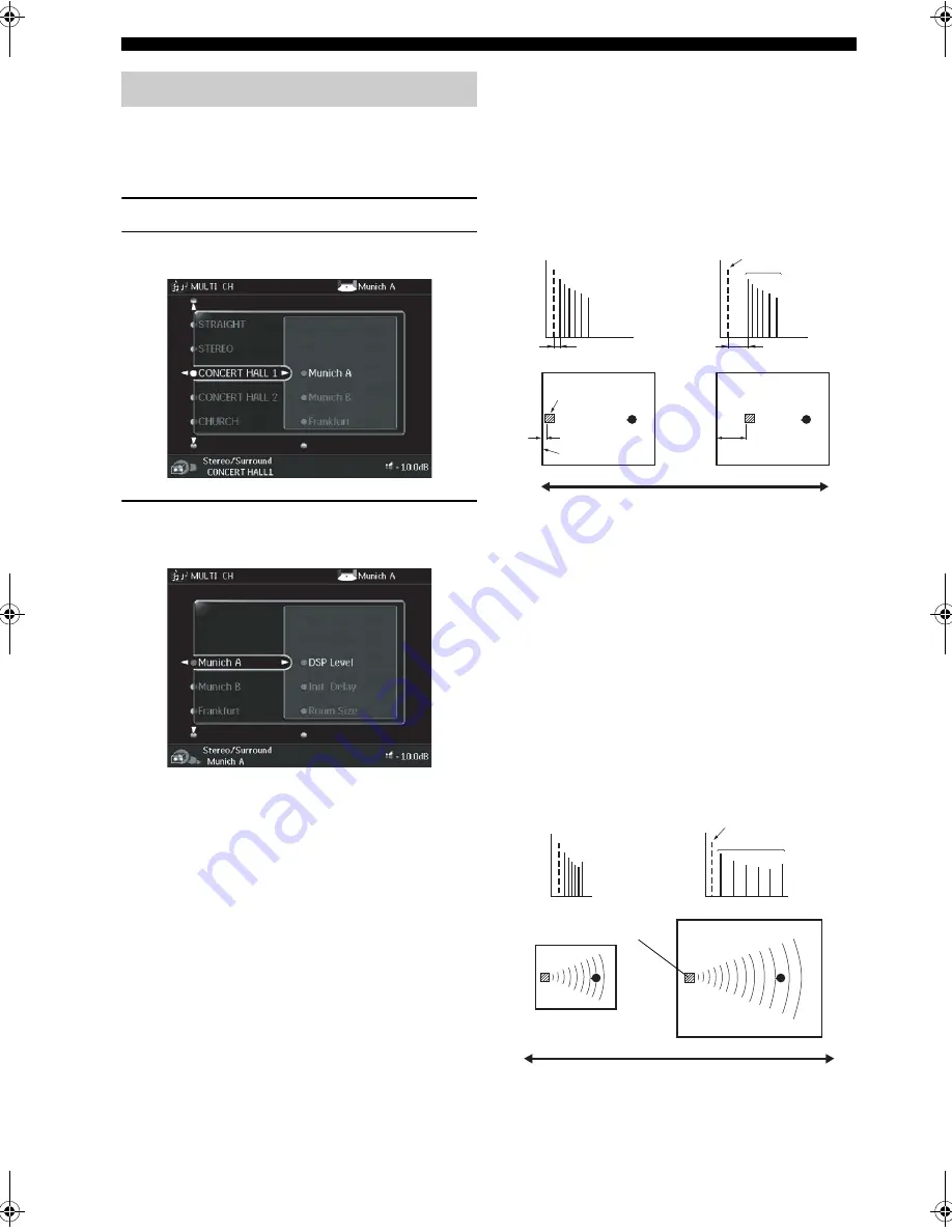
 DSP Level (DSP level)

This parameter adjusts the level of all DSP effect sounds 
within a narrow range. Depending on the acoustics of your 
listening room, you may want to increase or decrease the 
DSP effect level relative to the level of direct sound.
Control range: –6 dB – +3 dB

Init. Delay (Initial delay)

This parameter changes the apparent distance from the 
source sound by adjusting the delay between the direct 
sound and the first reflection heard by the listener. The 
smaller the value, the closer the sound source seems to the 
listener. The larger the value, the farther it seems. For a 
small room, set to a small value. For a large room, set to a 
large value.
Control range: 1


99 msec

Room Size (Room size)

This parameter adjusts the apparent size of the sound field. 
The larger the value, the larger the sound field becomes. 
As sound is repeatedly reflected around a room, the larger 
that room is, the longer the time between the original 
reflected sound and the subsequent reflections. By 
controlling the time between the reflected sounds, you can 
change the apparent size of the virtual venue. Changing 
this parameter from one to two doubles the apparent 
length of the room.
Control range: 0.1 – 2.0

Stereo/Surround menu

Source sound

Early 
reflections

Le

v

el

Le

v

el

INIT. DLY

INIT. DLY

Time

Time

Sound source

Reflection face

Small value = 1 ms

Large value = 99 ms

Source sound

L

eve

l

Time

L

eve

l

Time

Early 
reflections

Sound source

Large value = 2.0

Small value = 0.1

00EN.00_RXZ9_U.book  Page 110  Thursday, November 13, 2003  12:30 PM

Summary of Contents for RX Z9 - AV Receiver

Page 1: ...E 2 INPUT MODE SOURCE REMOTE DVD DTV LD MD TAPE CD R TUNER CD VIDEO AUX VCR 2 VCR 1 SAT CABLE A B STRAIGHT EFFECT MULTI CH INPUT DSP PROGRAM BALANCE TONE CONTROL VOLUME INPUT SELECTOR MULTI JOG SILENT OPTIMIZER MIC PHONES OPTICAL R AUDIO L VIDEO S VIDEO AV Receiver OWNER S MANUAL ...

Page 2: ...ng label If you are not sure of the type of power supply to your home consult your product dealer or local power company For products intended to operate from battery power or other sources refer to the operating instructions 12 Grounding or Polarization This product may be equipped with a polarized alternating current line plug a plug having one blade wider than the other This plug will fit into ...

Page 3: ... to Article 820 40 of the NEC that provides guidelines for proper grounding and in particular specifies that the cable ground shall be connected to the grounding system of the building as close to the point of cable entry as practical FCC INFORMATION for US customers 1 IMPORTANT NOTICE DO NOT MODIFY THIS UNIT This product when installed as indicated in the instructions contained in this manual mee...

Page 4: ...eld responsible for any damage resulting from use of this unit with a voltage other than specified 13 To prevent damage by lightning disconnect the power cord from the wall outlet during an electrical storm 14 Do not attempt to modify or fix this unit Contact qualified YAMAHA service personnel when any service is needed The cabinet should never be opened for any reasons 15 When not planning to use...

Page 5: ...g preset stations 52 RECORDING 53 SOUND FIELD PROGRAM DESCRIPTIONS 55 For movie video sources 55 For music sources 58 ADVANCED OPERATIONS 60 Selecting the OSD mode 60 Using the sleep timer 60 Using the test tone 61 SYSTEM OPTIONS 62 Changing parameter settings 64 Input Select 65 Manual setup Sound 68 Manual setup Basic 71 Manual setup Video 78 Manual setup Option 82 Memory Guard 85 REMOTE CONTROL ...

Page 6: ...a True Life Enhancer for smooth video images TBC Time Base Corrector for jitterless video images i LINK interface for direct digital transfer of digital audio signals Optical and coaxial digital audio signal jacks Sleep timer Night listening mode Remote control with preset manufacturer codes and learning macro capability Zone 2 custom installation facility y indicates a tip for your operation Some...

Page 7: ...TV VOL CH PRESET DISC EFFECT ON SCREEN TEST SLEEP PUSH TV MUTE MUSIC ENTERTAIN ROCK HALL 1 HALL 2 CHURCH NIGHT DTS CHP INDEX A B C D E SELECT DISPLAY SEARCH SOURCE PLAY ENTER DTV LD VCR 1 CD R MD TAPE SAT CABLE POWER V AUX 1 5 9 6 0 10 100 7 8 2 3 4 SPEAKERS A B Remote control Batteries 3 AA LR6 Power cord Optimizer microphone Speaker terminal wrench Batteries 2 AAA R03 POWER VOL MUTE TOP EXIT SYS...

Page 8: ...ries AA LR6 according to the polarity markings and on the inside of the battery compartment 3 After new batteries are correctly inserted press the RESET button in the battery compartment using a ball point pen or similar object This does not clear the contents of the memory 4 Replace the cover by pressing until it snaps into place GUI remote control 1 Press the part and slide the battery compartme...

Page 9: ...o two or more input jacks on this unit see page 46 7 MULTI CH INPUT Selects the source connected to the MULTI CH INPUT jacks This source takes priority over the source selected with INPUT SELECTOR or the input selector buttons on the remote control 8 STRAIGHT EFFECT Switches the sound fields off or on When STRAIGHT is selected input signals 2 channel or multi channel are output directly from their...

Page 10: ...ect to the audio video recorder and ZONE 2 outputs independently of the source you are listening to or watching in the main room When set to the SOURCE REMOTE position the input source is directed to all outputs The source in Zone 2 and the source you record are always identical H VIDEO AUX jacks Inputs audio and video signals from a portable external source such as a game console To reproduce sou...

Page 11: ...TO i LINK DTS DIGITAL D D RF ANALOG received when one component is connected to two or more input jacks on this unit see page 46 A 10KEY AMP Slide to 10KEY to select a numeric button or operate the component selected using the input selector buttons Slide to AMP to operate this unit B EX ES Switches between 5 1 and 6 1 7 1 channel playback of multi channel software C ON SCREEN Selects the GUI disp...

Page 12: ... EFFECT Switches the sound fields off or on When STRAIGHT is selected input signals 2 channel or multi channel are output directly from their respective speakers without effect processing S SPEAKERS A B Turn on or off the set of front speakers connected to the A and or B terminals on the rear panel each time the corresponding button is pressed T Cover Slide down to use the concealed buttons for va...

Page 13: ... of conditions high humidity such as near a bath high temperature such as near a heater or stove extremely low temperatures dusty locations Using the remote controls PHONO DVR PURE DIRECT 2CH 8CH SPEAKERS VIDEO AUX REC OUT ZONE 2 INPUT MODE SOURCE REMOTE DVD DTV LD MD TAPE CD R CD TUNER VIDEO AUX VCR 2 VCR 1 SAT CABLE A B STRAIGHT EFFECT MULTI CH INPUT DSP PROGRAM TUNING MODE MEMORY FM AM PRESET T...

Page 14: ...E level indicators Indicates the volume level B MUTE indicator Lights up when the MUTE function is on C LFE indicator Lights up when the input signal contains the LFE signal D THX indicators Lights up when a THX program is selected E PCM indicator Lights up when this unit is reproducing PCM pulse code modulation digital audio signals F OPTIMIZER indicator Lights up during the auto setup procedure ...

Page 15: ...ghts up when the sleep timer is on N Multi information display Shows the current sound field program name and other information when adjusting or changing settings O Input channel indicators Indicates the channel component of the current digital input signal Presence DSP sound field Listening position Surround left DSP sound field Surround right DSP sound field Surround back DSP sound field ...

Page 16: ...al This is a control expansion terminal for commercial use Consult you dealer for details I ZONE 2 audio jacks See page 100 for details J FRONT IN CENTER IN See page 27 for connection information General models only VOLTAGE SELECTOR See page 29 for details Rear panel L L R R FRONT A FRONT B FRONT B FRONT A SURROUND SUBWOOFER FRONT PURE DIRECT CD DVD DTV LD CBL SAT VCR 1 IN PLAY MD TAPE CD R OUT RE...

Page 17: ...akers and provide for more realistic front to back transitions Place these speakers directly behind the listening position and at the same height as the surround speakers They should be positioned at least 30 cm 12 in apart Ideally they should be positioned at the same width as the front speakers Subwoofer The use of a subwoofer such as the YAMAHA Active Servo Processing Subwoofer System is effect...

Page 18: ...h the monitor place the speakers away from the monitor A speaker cord is actually a pair of insulated cables running side by side One cable is colored or shaped differently perhaps with a stripe groove or ridges Connect the striped grooved etc cable to the red terminals on this unit and your speaker Connect the plain cable to the black terminals 1 Remove approximately 10 mm 3 8 of insulation from ...

Page 19: ...EAKERS PRESENCE ZONE 2 SUBWOOFER REAR FRONT R 1 2 4 11 9 7 3 6 8 5 10 Right subwoofer system Center speaker Front right speaker A Surroundback right speaker Surround right speaker 1 2 3 4 5 6 10 11 9 8 7 Speaker layout Presence right speaker Presence left speaker Surround back left speaker Front left speaker A Surround left speaker Left subwoofer system Front speakers B ...

Page 20: ...ont panel display CENTER terminals Connect a center speaker to these terminals SURROUND terminals Connect a surround speaker system to these terminals SUBWOOFER jacks Connect one or two subwoofer s with built in amplifier such as the YAMAHA Active Servo Processing Subwoofer System to the jack s SURROUND BACK terminals Connect a surround back speaker system to these terminals If you only connect on...

Page 21: ...ected with i LINK equipped components using 4 pin S400 i LINK cables This connection enables you to send and receive digital audio at high speed and with high fidelity Video jacks This unit has three types of video jacks The signals input through any type of VIDEO IN jack can be output through any of the VIDEO MONITOR OUT jacks automatic video conversion VIDEO jack For conventional composite video...

Page 22: ...NE 2 SPEAKERS AC I L R CENTER SINGLE PHONO SURROUND BACK SURROUND GND MULTI CH INPUT 2CH IN IN PLAY COMPONENT VIDEO DVD 1 MONITOR OUT 2 DTV LD Y PB PR DVD CBL SAT VCR1 DVR DTV LD 1 MONITOR OUT 2 DIGITAL INPUT q RF DTV LD DTV SAT CD CD CD R CD R MD T DVD DVD DVR CBL DVR A B C D E F 1 2 4 3 5 6 7 8 9 0 B A S1 S2 AC 3 COAXIAL LD L C R O DVD player Video monitor Optical out Video out Audio out Video i...

Page 23: ... channels Connecting to the 2CH IN jacks This unit is equipped with 2 additional input jacks for discrete 2 channel input from a universal disc player passive input selector or other high speed audio component The signals input to these jacks can be chosen by pressing PURE DIRECT see page 45 This feature provides the best possible sound quality from this unit Connect the output jacks on your multi...

Page 24: ...AY MD TAPE CD R OUT REC OUT REC CENTER SURROUND BACK PRESENCE ZONE 2 SPEAKERS AUDIO AC OUTLETS AC IN L R CENTER SINGLE PHONO SURROUND BACK SURROUND GND MULTI CH INPUT 2CH IN IN PLAY IN PLAY OUT REC VCR IN PLAY IN VCR 1 OUT IN VCR COMPONENT VIDEO VIDEO DVD 1 MONITOR OUT 2 DTV LD CBL SAT Y PB PR DVD CBL SAT VCR1 DVR DTV LD 1 MONITOR OUT 2 DIGITAL INPUT q RF DTV LD DTV SAT CD CD CD R CD R MD TAPE DVD...

Page 25: ...CENTER SINGLE PHONO SURROUND BACK SURROUND GND MULTI CH INPUT 2CH IN IN PLAY IN PLAY OUT REC VCR IN PLAY IN VCR 1 OUT IN VCR COMPONENT VIDEO VIDEO DVD 1 MONITOR OUT 2 DTV LD CBL SAT Y PB PR DVD CBL SAT VCR1 DVR DTV LD 1 MONITOR OUT 2 DIGITAL INPUT q RF DTV LD DTV SAT CD CD CD R CD R MD TAPE DVD DVD DVR DVR OPTICAL COAXIAL ZONE 2 CBL DVR DIGITAL OUTPUT A B C D E F 1 2 4 3 5 6 7 8 9 0 B A C D S1 S2 ...

Page 26: ...GLE PHONO SURROUND BACK SURROUND GND MULTI CH INPUT 2CH IN IN PLAY IN PLAY OUT REC VCR IN PLAY IN VCR 1 OUT IN VCR COMPONENT VIDEO VIDEO DVD 1 MONITOR OUT 2 DTV LD CBL SAT Y PB PR DVD CBL SAT VCR1 DVR DTV LD 1 MONITOR OUT 2 DIGITAL INPUT q RF DTV LD DTV SAT CD CD CD R CD R MD TAPE DVD DVD DVR DVR OPTICAL COAXIAL ZONE 2 CBL DVR DIGITAL OUTPUT A B C D E F 1 2 4 3 5 6 7 8 9 0 B A C D S1 S2 AC 3 COAXI...

Page 27: ...CENTER SINGLE PHONO SURROUND BACK SURROUND GND MULTI CH INPUT 2CH IN IN PLAY IN PLAY OUT REC VCR 2 IN PLAY OUT REC IN VCR 1 OUT IN VCR 2 OUT COMPONENT VIDEO VIDEO DVD 1 MONITOR OUT 2 DTV LD CBL SAT Y PB PR DVD CBL SAT VCR1 DVR DTV LD 1 MONITOR OUT 2 DIGITAL INPUT q RF DTV LD DTV SAT CD CD CD R CD R MD TAPE DVD DVD DVR DVR OPTICAL COAXIAL ZONE 2 CBL DVR DIGITAL OUTPUT A B C D E F 1 2 4 3 5 6 7 8 9 ...

Page 28: ...PLAY IN PLAY OUT REC VCR 2 IN PLAY OUT REC DVR IN PLAY OUT REC OUT ZONE 2 IN VCR 1 OUT IN VCR 2 OUT IN DVR OUT ZONE 2 COMPONENT VIDEO VIDEO DVD 1 MONITOR OUT 2 DTV LD CBL SAT CBL SAT VCR1 DVR 1 MONITOR OUT 2 DIGITAL INPUT DTV SAT CD CD R CD R MD TAPE DVD DVD DVR DVR OPTICAL COAXIAL ZONE 2 CBL DVR DIGITAL OUTPUT C D E F 4 3 5 6 7 8 9 0 B A C D S400 AUDIO S1 S2 O O L R C L R DVD recorder Audio out V...

Page 29: ...al with some record players Connecting audio components R R FRONT A FRONT B SURROUND SUBWOOFER FRONT PURE DIRECT CD DVD DTV LD CBL SAT IN PLAY MD TAPE CD R OUT REC OUT REC CENTER SURROUND BACK PRESENCE ZONE 2 SPEAKERS AUDIO AC IN L R CENTER SINGLE PHONO SURROUND BACK SURROUND GND MULTI CH INPUT 2CH IN IN PLAY COMPONENT VIDEO DVD 1 MONITOR OUT 2 DTV LD CBL SAT Y PB PR DVD CBL SAT VCR1 DVR DTV LD 1 ...

Page 30: ...NGLE PHONO SURROUND BACK SURROUND GND MULTI CH INPUT 2CH IN IN PLAY COMPONENT VIDEO DVD 1 MONITOR OUT 2 DTV LD CBL SAT Y PB PR DVD CBL SAT VCR1 DVR DTV LD 1 MONITOR OUT 2 DIGITAL INPUT q RF DTV LD DTV SAT CD CD CD R CD R MD TAPE DVD DVD DVR DVR OPTICAL CBL DVR DIGITAL OUTP A B C D E F 1 2 4 3 5 6 7 8 9 0 B A C D S1 S2 AC 3 COAXIAL LD L R L R L R L R O O O MD tape CD recorder Audio in Audio out Opt...

Page 31: ...he YAMAHA Active Servo Processing Subwoofer System to these jacks Adjust the volume level of the subwoofer with the control on the subwoofer It is also possible to adjust the volume level using this unit s remote control see page 76 Some signals may not be output from the SUBWOOFER jack depending on the Speaker Set see page 74 and LFE Level see page 70 settings Connecting external preamplifiers If...

Page 32: ...ndoor one If you experience poor reception quality an outdoor antenna may improve the quality Consult the nearest authorized YAMAHA dealer or service center about outdoor antennas FREQUENCY STEP switch General model only Because the interstation frequency spacing differs in different areas set the FREQUENCY STEP switch locating on the rear panel according to the frequency spacing in your area Nort...

Page 33: ...her models 100 W VOLTAGE SELECTOR General model only The VOLTAGE SELECTOR on the rear panel of this unit must be set to your local main voltage BEFORE plugging into the AC main supply Voltages are 110 120 220 230 240 V AC and 50 60 Hz Memory back up The memory back up circuit prevents the stored data from being lost even if this unit is in the standby mode However if the power cord is disconnected...

Page 34: ...nnected to this unit Speaker impedance setting CAUTION SPEAKERS A STANDBY ON MinimumA8ohms ASPAImp ASet Turning on the power PHONO DVR PURE DIRECT 2CH 8CH SPEAKERS VIDEO AUX REC OUT ZONE 2 INPUT MODE SOURCE REMOTE DVD DTV LD MD TAPE CD R CD TUNER VIDEO AUX VCR 2 VCR 1 SAT CABLE A B STRAIGHT EFFECT MULTI CH INPUT DSP PROGRAM TUNING MODE MEMORY FM AM PRESET TUNING BALANCE TONE CONTROL VOLUME INPUT S...

Page 35: ...and configure input sources Manually configure your system settings Automatically set up your system Protect your system settings Display information about audio and video signals 1 Switch on this unit and your video monitor Make sure the GUI is displayed 2 Press TOP The TOP display appears 3 Press k n repeatedly to select a category i e Manual Setup then press h to enter the selected category i e...

Page 36: ... see page 62 7 When finished press EXIT to exit All GUI remote control operations featured in this manual can also be performed using the main remote control When using the main remote control to perform these operations make sure that 10KEY AMP on the remote controller is set to AMP Note TOP EXIT ENTER MULTI CH IN PURE DIRECT TOP EXIT INPUT MODE SOUND TITLE MENU CHAPTER PAUSE STOP POWER REC SELEC...

Page 37: ... brands or sizes of speakers for some channels or have a room with unique sonic characteristics YPAO equalizing calibration incorporates three parameters Frequency Level and Q factor for each of the 10 bands in its parametric equalizer plus 5 subwoofer bands to provide highly precise automatic adjustment of frequency characteristics Level Checks and adjusts the sound level volume of each speaker 1...

Page 38: ...GUI remote control The TOP display appears 2 Press k n repeatedly to select Auto Setup then press h 3 Press k n repeatedly to select Setup Menu then press h 4 Press k n repeatedly to select Wiring Distance Size Equalizing or Level For Wiring Distance Size or Level select Check To automatically check and adjust the selected item Skip To skip the selected item and perform no adjustments y When using...

Page 39: ... selected the desired setting press l to move back to Setup Menu 6 Press n to select Setup Type then select Auto To automatically perform the entire auto setup procedure Step To pause for confirmation between each check in the auto setup procedure 7 Press n to select Start then press ENTER Loud test tones are output from each speaker and Measuring appears during the auto setup procedure To pause t...

Page 40: ...surement Over appears on the screen and the results for each item are displayed Press n and select Setup to set the measured values Press k and select Retry to retry the auto setup procedure Press h and select Detail to view information about measurement results and error or warning messages For more details about error and warning messages see Troubleshooting for the auto setup procedure on page ...

Page 41: ...back right channel signal is detected Connect the surround back speaker to the LEFT SURROUND BACK SPEAKERS terminal if you only have one surround back speaker E05 Noisy Background noise is too loud Try auto setup in a quiet environment Turn off noisy electric equipment like air conditioners or move it away from this unit E06 Check Surr Surround back speaker s is are connected though surround L R s...

Page 42: ...ncorrect This message may appear depending on the speakers even when they are connected correctly Check the speaker connections W2 Over24m 80ft The distance between the speaker and the listening position is over 24 m 80 ft Bring the speaker closer to the listening position W3 Level Error The difference in volume level between the speakers is excessive No level correction is made Readjust the speak...

Page 43: ...UX VCR 2 VCR 1 SAT CABLE A B STRAIGHT EFFECT MULTI CH INPUT DSP PROGRAM TUNING MODE MEMORY FM AM PRESET TUNING BALANCE TONE CONTROL VOLUME INPUT SELECTOR MULTI JOG SILENT MIC PHONES OPTICAL R AUDIO L VIDEO S VIDEO STANDBY ON 1 5 4 6 3 TRANSMIT RE NAME STANDBY TUNER MULTI CH IN PURE DIRECT TOP EXIT INPUT MODE SOUND SYSTEM CLEAR LEARN MACRO OFF ON MACRO PHONO CD DVD DVR VCR 2 TITLE MENU CHAPTER PAUS...

Page 44: ...ont panel to select Treble or Bass Select Treble then rotate MULTI JOG to the right or left to increase or decrease the high frequency response Select Bass then rotate MULTI JOG to the right or left to increase or decrease the low frequency response To cancel the tone control press TONE CONTROL repeatedly to select OFF If you increase or decrease the high frequency or low frequency sound to an ext...

Page 45: ...ULTI CH INPUT jacks together with a video source use the on screen display menu see BGV Background video on page 67 Front panel operation Press DSP PROGRAM then rotate MULTI JOG to select the desired program The name of the selected program appears on the front panel display and on the video monitor Note Note MULTI CH INPUT MULTI CH IN Front panel Remote control or TUNER PHONO CD DVD DVR VCR 2 DTV...

Page 46: ...ize the flag or no flag is present in the input signal it cannot automatically be played in 6 1 7 1 channels Decoders select with l h You can select from the following modes depending on the format of the software you are playing PLIIx Movie For playing back Dolby Digital DTS or analog multi channel signals in 7 1 channels using the Pro Logic IIx movie decoder PLIIx Music For playing back Dolby Di...

Page 47: ...els to 5 1ch 6 1 7 1 channel processing using the PLIIx decoder or 7 1ch plays back external 7 1 channel signals as they are Enjoying 2 channel software Signals input from 2 channel sources can also be played back on multiple channels using the Dolby Pro Logic Dolby Pro Logic II Dolby Pro Logic IIx or DTS Neo 6 decoders Press q DTS on the remote control to switch between Surround Standard or Surro...

Page 48: ... set to None see page 74 Listening to unprocessed sound Press STRAIGHT EFFECT to select STRAIGHT 2 channel stereo sources are output from the front left and right speakers only Multi channel sources are decoded straight into the appropriate channels without any additional effect processing Press STRAIGHT EFFECT again so that STRAIGHT disappears from the display when you want to turn the sound effe...

Page 49: ...gh quality sound select the STEREO Direct sound field program The program works with analog PCM and DSD sources Press DSP PROGRAM then rotate MULTI JOG or set 10KEY AMP to AMP and press STEREO repeatedly on the remote control to select STEREO Direct STEREO Direct Analog appears for 2 channel analog sources STEREO Direct PCM appears for PCM digital audio sources STEREO Direct DSD appears for Super ...

Page 50: ...s unit selects when the power is turned on see page 83 If MULTI CH IN is selected you cannot change the input source using INPUT SELECTOR Press MULTI CH IN on the remote control or MULTI CH INPUT on the front panel to remove the selection You can also perform this operation using the GUI remote control see page 31 When playing back CD or LD sources encoded in DTS set the input mode to DTS If the d...

Page 51: ... channels 2 surround channels and LFE is displayed as 3 2 0 1 Bitrate Bit rate When the unit is unable to detect the bit rate Unknown appears Dialog Dialog normalization information for Dolby Digital signals Flag 1 Flag 2 A signal format capable of identifying special operation commands contained in audio input signals Video signal information Resolution Resolution for video input output signals W...

Page 52: ...n band following steps 1 and 2 as described in Automatic tuning 2 Press TUNING MODE so that the AUTO indicator disappears from the front panel display If a colon appears on the front panel display press PRESET TUNING to turn it off TUNING Automatic and manual tuning PHONO DVR PURE DIRECT 2CH 8CH SPEAKERS VIDEO AUX REC OUT ZONE 2 INPUT MODE SOURCE REMOTE DVD DTV LD MD TAPE CD R TUNER CD VIDEO AUX V...

Page 53: ...tations does not reach E8 automatic preset tuning has automatically stopped after searching all stations Only FM stations with sufficient signal strength are stored automatically by automatic preset tuning If the station you want to store is weak in signal strength tune in to it manually in the monaural mode and store it by following the procedure in Manually presetting stations Automatic preset t...

Page 54: ... station frequency Memory back up The memory back up circuit prevents the stored data from being lost even if this unit is set in the standby mode the power cord is disconnected from the AC outlet or the power supply is temporarily cut due to power failure However if the power is cut for more than one week the preset stations may be cleared If so store the stations again by using the presetting st...

Page 55: ...tward to select a higher preset station group and number Rotate leftward to select a lower preset station group and number Selecting preset stations STEREO EX ES AMP 10KEY ROCK MOVIE THX MUTE VOLUME STRAIGHT TV INPUT TV VOL CH PRESET DISC EFFECT ON SCREEN TEST SLEEP TV MUTE MUSIC TV THTR ENTERTAIN HALL CHURCH JAZZ NIGHT DTS CHP INDEX A B C D E 1 5 9 6 0 10 100 7 8 2 3 4 SPEAKERS A B PUSH 1 2 1 2 M...

Page 56: ...2CH 8CH SPEAKERS VIDEO AUX REC OUT ZONE 2 INPUT MODE SOURCE REMOTE DVD DTV LD MD TAPE CD R TUNER CD VIDEO AUX VCR 2 VCR 1 SAT CABLE A B STRAIGHT EFFECT MULTI CH INPUT DSP PROGRAM TUNING MODE MEMORY FM AM PRESET TUNING BALANCE TONE CONTROL VOLUME INPUT SELECTOR MULTI JOG SILENT MIC PHONES OPTICAL R AUDIO L VIDEO S VIDEO STANDBY ON 2 1 PRESET TUNING E1 FM 87 5 MHz MULTI CH V AUX DVR VCR 1 VCR 2 DTV ...

Page 57: ...y through this unit s video circuits Therefore when recording or dubbing video signals if your video source component is connected to provide only an S video or composite video signal you can record only an S video or composite video signal to your VCR A given input source is not output on the same REC OUT channel For example the signal input from VCR 1 IN is not output on VCR 1 OUT Check the copy...

Page 58: ...oise being recorded Therefore if you want to use this unit to record sources that have DTS signals recorded on them the following considerations and adjustments need to be made For LDs DVDs and CDs encoded with DTS when your player is compatible with the DTS format follow its operation instructions to make a setting so that the analog signal is output from the player ...

Page 59: ...t hall MUSIC VIDEO Pavillion This program reproduces vocals clearly letting you feel the spaciousness of a pavilion Reverberation which is somewhat delayed reproduces the live acoustics unique to a pavilion and helps to make concert scenes more exciting MOVIE THEATER Spectacle CINEMA DSP processing This program creates the extremely wide sound field of a 70 mm movie theater It precisely reproduces...

Page 60: ...ram provides additional CINEMA DSP processing SUR STANDARD Dolby Digital EX Standard 6 1 channel processing for Dolby Digital EX sources The ENHANCED version of this program provides additional CINEMA DSP processing SUR STANDARD qD PLIIx Movie Standard Dolby Digital and Dolby Pro Logic IIx Movie processing SUR STANDARD qD PLIIx Music Standard Dolby Digital and Dolby Pro Logic IIx Music processing ...

Page 61: ...NDARD Pro Logic Standard processing for Dolby Surround sources The ENHANCED version of this program provides additional CINEMA DSP processing 2 CH SUR STANDARD PLII Movie Standard Dolby Pro Logic II processing for movie software SUR STANDARD PLII Game Standard Dolby Pro Logic II processing for game software SUR ENHANCED Pro Logic II CINEMA DSP enhanced processing for sources decoded by the PRO LOG...

Page 62: ...t section on the first floor CONCERT HALL1 Stuttgart HiFi DSP processing This is a large asymmetrical concert hall with around 2000 seats located in downtown Stuttgart Sound reflected off the concrete wall located to the left of listeners has a powerful presence CONCERT HALL1 Vienna HiFi DSP processing A classic shoe box type concert hall with approximately 1700 seats Pillars and ornate carvings c...

Page 63: ...ub The floor can seat 300 people to the left and right in a sound field offering a real and vibrant sound ROCK CONCERT The Roxy Theatre HiFi DSP processing The ideal program for lively dynamic rock music The data for this program was recorded at LA s hottest rock club The listener s virtual seat is at the center left of the hall ROCK CONCERT Warehouse Loft HiFi DSP processing This program simulate...

Page 64: ...isplay changes as shown below The SLEEP indicator flashes while switching the amount of time for the sleep timer The SLEEP indicator lights up on the front panel display after the sleep timer has been set Canceling the sleep timer Press SLEEP repeatedly until Sleep Off appears on the front panel display After a few seconds Sleep Off disappears and the Sleep indicator goes off y The sleep timer set...

Page 65: ... against that of the front left speaker 3 Press l h to adjust the speaker volumes 4 Press TEST once more when you have completed your adjustment The test tone stops y Use a handheld SPL meter hold at arms length and point upwards so that the meter is in the listening position With the meter set to the 70 dB scale and to C SLOW calibrate each speaker to 75 dB Before outputting the test tone we reco...

Page 66: ...ame of the input 66 Analog Level Selects the analog input level 67 BGV Selects the video source to be output when MULTI CH is selected 67 Input Channels Selects the number of audio channels input through the MULTI CH INPUT jacks 67 Item Features Page Cinema EQ Adjusts the source sound to your liking 68 Graphic EQ Adjusts the tonal quality of each speaker 68 Tone Control Adjusts the tonal balance o...

Page 67: ...processor 78 Picture Mode Selects and adjusts the video picture mode suitable for the video picture 79 Resolution Selects the video resolution 79 Aspect Selects the aspect ratio 80 Cross Color Removes noise from image brightness 81 TV Format Selects the video format 81 S Video Selects the output of video devices 82 Item Features Page Surr Initialize Initializes the parameters of all or a group of ...

Page 68: ...ct a menu then press h to enter the selected menu 3 Press k n repeatedly to select the parameter you want to adjust 4 Press ENTER or h then press k n repeatedly to change the setting of the item you want to adjust 5 Press EXIT y If you want to continue adjusting parameter settings press ENTER to return to the previously selected menu item Changing parameter settings TOP EXIT ENTER 2 2 4 4 5 80Hz T...

Page 69: ... the input signal Input Select input source DVD etc Mode Choices Auto D D RF DTS Digital iLINK Analog y This menu is only available for input sources that have been assigned digital jacks Before you can select iLINK you must first connect this unit to an i LINK component and assign it to an input Before you can select D D RF you must first select DTV LD as the input source and then specify 1 LD RF...

Page 70: ...signment Coaxial Input Optical Input Optical Output or Component Video 3 Select None then press ENTER to clear the assignment You cannot select a specific item more than once for the same type of jack When you connect a component to both the COAXIAL and OPTICAL jacks priority is given to the input signals from the COAXIAL jack If you want to use the COAXIAL 1 DTV LD jack to input Dolby Digital RF ...

Page 71: ...e the last video input source that was selected Select OFF if you do not want a video image to be output Even when Last is selected the last video input source selected will not be used after PURE DIRECT is selected or this unit is set to standby mode Input Channels Input channels Use this feature to specify the number of audio channels input through the MULTI CH INPUT jacks Input Select MULTI CH ...

Page 72: ... selected you can set a frequency between 1 0 and 12 7 kHz and a level between 9 and 3 dB Front Center adjusts levels for the front left front right and center speakers Surround adjusts levels for the surround left and surround right speakers Surround Back adjusts levels for the surround back left and surround back right speakers Presence adjusts levels for the front presence left and right speake...

Page 73: ...s the tonal quality of the surround right speaker Surround Back L adjusts the tonal quality of the surround back left speaker Surround Back R adjusts the tonal quality of the surround back right speaker Presence L adjusts the tonal quality of the presence left speaker Presence R adjusts the tonal quality of the presence right speaker Cinema EQ and Graphic EQ adjustments do not affect the output to...

Page 74: ... Select to adjust the headphone LFE level Depending on the settings of LFE Level some signals may not be output from the SUBWOOFER jack Dynamic Range Dynamic range Use to select the amount of dynamic range compression to be applied to your speakers and headphones This setting is effective only when the unit is decoding Dolby Digital and DTS signals To access these parameters select Manual Setup So...

Page 75: ...ic system parameters 1 Press TOP on the GUI remote control 2 Select Manual Setup then press h 3 Select Basic then press h 4 Select the desired parameters then press h to access and adjust y Most of the parameters described in the basic menu are set automatically when you run auto setup You can use the basic menu to make further adjustments but we recommend running auto setup first You can reset th...

Page 76: ...mp function Select On to use the Bndry Gain Comp function SB Speaker Dist Surround back speaker distance Use this feature to optimize the surround sound field when you have to place the surround back speakers apart Choices U S A and Canada models under 1ft 1 4ft over 4ft Other models under 0 3m 0 3 1 2m over 1 2m Select under 0 3m or under 1ft if the distance between the two surround back speakers...

Page 77: ...field Select None if you do not have any subwoofers Phase Phase If bass sounds are lacking or unclear use this feature to adjust the frequency phase characteristics of your subwoofer s Try reversing the phase for both the left and right subwoofer speakers together using L R Reverse and if the sound is still not satisfactory try adjusting the phase for these speakers individually Choices Normal L R...

Page 78: ...w frequency and LFE signals to the front speakers even if you have previously set Front to Small in Speaker Set Speaker Set Speaker set Use to manually adjust any speaker setting Manual Setup Basic Speaker Set Set any THX speakers to Small Front Front speakers Choices Large Small Select Large if you have large front speakers The unit directs the entire range of the front left and right channel sig...

Page 79: ...t Large x1 if you have a large surround back speaker The unit directs the entire range of the surround back channel signal to the surround back left speaker Select Small x1 if you have a small surround back speaker The low frequency signals of the surround back channel are directed to the speakers selected with Bass Out and the rest of the frequency signals are directed to the surround back left s...

Page 80: ...dB Front L adjusts the balance of the front left speaker Front R adjusts the balance of the front right speaker Center adjusts the balance of the center speaker Surround L adjusts the balance of the surround left speaker Surround R adjusts the balance of the surround right speaker Surround Back L adjusts the balance of the surround back left speaker Surround Back R adjusts the balance of the surro...

Page 81: ...ker distances in feet Choices 0 3 to 24 00 m 1 to 80 ft Initial setting for all speakers U S A and Canada models 10 0 feet Other models 3 0 meters Front L adjusts the distance of the front left speaker Front R adjusts the distance of the front right speaker Center adjusts the distance of the center speaker Surround L adjusts the distance of the surround left speaker Surround R adjusts the distance...

Page 82: ...me game machines 1 Press TOP on the GUI remote control 2 Select Manual Setup then press h 3 Select Video then press h 4 Select the desired parameters then press h to access and adjust Processor Processor Use this feature to turn on off the digital video processors Manual Setup Video Processor Choices Off On Select Off to turn off the digital video processors Select On to turn on the digital video ...

Page 83: ...rightness Select Contrast to adjust the contrast Select Saturation to adjust the depth of color Select Reset then press h to cancel the picture adjustment With some monitors making extreme adjustments to several items may result in video distortion In such cases select Reset to cancel the picture adjustments and use the video adjustment features provided on your monitor Resolution Resolution Use t...

Page 84: ...way Auto Automatically detects the aspect ratio of the input video signal and chooses the most appropriate setting automatically 16 9 Normal Adds black bars to the left and right sides of the input video signal before outputting it to the TV Use to watch 4 3 software on a 16 9 TV 16 9 Zoom Cuts off the top and bottom of the input video signal before outputting it to the TV Use to watch 4 3 letter ...

Page 85: ... displayed images Select Suppress to remove noise from the brightness of displayed images TV Format TV format Use this feature to select the video format for your TV Manual Setup Video TV Format Choices PAL NTSC Initial setting U S A Canada Korea and General models NTSC Europe U K Australia and China PAL If no image signal is being input for the selected TV format select the format for the signal ...

Page 86: ...up Video S Video Choices S S1 S2 Select S when connecting this unit to the S input terminal on your monitor Select S1 when connecting this unit to the S or S1 video input terminals on your monitor Select S2 when connecting this unit to the S2 video input terminals on your monitor This menu adjusts the optional system settings 1 Press TOP on the GUI remote control 2 Select Manual Setup then press h...

Page 87: ...se the numeric keys on the remote control to select the sound field program you want to initialize then press ENTER Select EXIT then press ENTER to exit this menu Sound field program groups cannot be initialized when Memory Guard Surr Parameter is set to Guard see page 85 Input Mode Input mode Use this feature to designate the input mode for sources connected to the DIGITAL INPUT jacks when you tu...

Page 88: ...n off the text information OSD Select On to turn on the text information OSD When Aspect is set to 16 9 Zoom see page 80 the OSD is not displayed even if On Screen is set to On Dimmer Dimmer Use to adjust the brightness of the front panel display Choices 4 to 0 Multi Zone Multi zone Use this feature to customize the Zone 2 and Zone B settings Manual Setup Option Multi Zone Speaker B Speaker B Use ...

Page 89: ...n the remote control Zone2 Tuner Sel Zone 2 tuner select U S A Canada and Australia models only Use this feature to enable disable the tuner function in Zone 2 Choices Enable Disable Select Enable to use the tuner function in Zone 2 Select Disable if you do not want to use the tuner function in Zone 2 Use this feature to prevent accidental changes to individual parameter settings 1 Press TOP on th...

Page 90: ... setup parameters Auto Setup Auto setup Choices Free Guard Select Guard to prevent changes to the auto setup parameters Even when Guard is set you can change the Distance unit Select Free to enable changes to the auto setup parameters In general front panel and remote control operations are not affected by Guard functions However you cannot do the following Adjust the tone control Switch the input...

Page 91: ...CT TOP EXIT INPUT MODE SOUND SYSTEM CLEAR LEARN MACRO OFF ON MACRO PHONO CD DVD DVR VCR 2 TITLE MENU CHAPTER PAUSE STOP POWER REC STEREO EX ES AMP 10KEY JAZZ MOVIE THX MUTE VOLUME STRAIGHT TV INPUT TV VOL CH PRESET DISC EFFECT ON SCREEN TEST SLEEP PUSH TV MUTE MUSIC ENTERTAIN ROCK HALL 1 HALL 2 CHURCH NIGHT DTS CHP INDEX A B C D E SELECT DISPLAY SEARCH SOURCE PLAY ENTER DTV LD VCR 1 CD R MD TAPE S...

Page 92: ...o YPC to operate this unit However you can switch between the following four codes if necessary YPC To operate this unit without ZONE 2 features ZONE To operate this unit with ZONE 2 features DSP To operate YAMAHA DSP amplifiers that cannot be operated with the YPC code NO To operate the amplifiers of other manufacturers using this unit s remote control 3 Press k n to select the name of your compo...

Page 93: ... to the operation instructions for the remote control of your component 1 Set 10KEY AMP to 10KEY y It is also possible to program in this unit s control area with 10KEY AMP set to AMP However if you do this you will not be able to control this unit and select sound field programs 2 Press an input selector button to select a source component 3 Place this remote control about 5 to 10 cm away from th...

Page 94: ...isplay window if you press more than one button at the same time You can change the name that appears in the display window on the remote control if you want to use a different name to the one that is factory preset This is useful when you have set the input selector to control another component 1 Press an input selector button to select the source component you want to rename The selected compone...

Page 95: ... to the operation instructions for the connected component 2 Playback can be started for any YAMAHA remote control compatible MD recorder CD player CD recorder DVD player or LD player When using macros to operate other components you will need to program the PLAY button on the control area of that component see pages 89 and 90 or set a manufacturer code see page 88 3 When TUNER is selected as the ...

Page 96: ...s MACRO again 2 Press the macro button you want to use to operate the macro The macro button name and the selected component name appear alternately in the display window AGAIN appears in the display window if you press a button other than a macro button To change the selected source component press SOURCE SELECT k n Pressing the input selector buttons will program a macro step whereas SOURCE SELE...

Page 97: ...ent source names FCTRY Clears all remote functions and returns the remote to the factory settings 3 Press and hold CLEAR again for about 3 seconds C OK appears in the display window C NG appears in the display window if the operation was unsuccessful In this case start over from step 2 4 Press CLEAR to exit the clear mode Once you have cleared a learned function or macro for a button the button re...

Page 98: ...r learned functions 5 Press LEARN to exit the clear mode Clearing macro functions 1 Press MACRO using a ballpoint pen or similar object y Complete each of the following steps within 30 seconds Otherwise the learning mode is automatically canceled In this case press MACRO again 2 Press and hold CLEAR using a ballpoint pen or similar object then press the macro button you want to clear for about 3 s...

Page 99: ... VCR VCR 1 VCR 2 and V AUX areas Controlling components TITLE SEARCH POWER Return STOP Title Index TV operation MENU DISPLAY Menu cursor ENTER PLAY PAUSE Numeric buttons Clear DISC disc skip Audio Skip search MULTI CH IN PURE DIRECT TOP EXIT INPUT MODE SOUND DVD DVR VCR 2 TITLE MENU CHAPTER PAUSE STOP POWER REC STEREO EX ES AMP 10KEY JAZZ MOVIE THX MUTE VOLUME STRAIGHT TV INPUT TV VOL CH PRESET DI...

Page 100: ...AMP 10KEY JAZZ MOVIE THX MUTE VOLUME STRAIGHT TV INPUT TV VOL CH PRESET DISC EFFECT TV MUTE MUSIC ENTERTAIN ROCK HALL 1 HALL 2 CHURCH NIGHT DTS CHP INDEX A B C D E SELECT DISPLAY SEARCH SOURCE PLAY ENTER DTV LD VCR 1 CD R MD TAPE SAT CABLE POWER V AUX 1 5 9 6 0 10 100 7 8 2 3 4 DISPLAY POWER Enter TV VOL TV MUTE 1 Numeric buttons MENU Menu cursor Select CABLE and SAT only Recall CABLE and SAT only...

Page 101: ...R MD TAPE SAT CABLE POWER V AUX 1 5 9 6 0 10 100 7 8 2 3 4 DISPLAY SEARCH POWER STOP INDEX TV operation Skip search DISC disc skip PLAY PAUSE Numeric buttons Clear STANDBY TUNER MULTI CH IN PURE DIRECT TOP EXIT INPUT MODE SOUND SYSTEM PHONO CD DVD DVR VCR 2 TITLE MENU CHAPTER PAUSE STOP POWER REC STEREO EX ES AMP 10KEY JAZZ MOVIE THX MUTE VOLUME STRAIGHT TV INPUT TV VOL CH PRESET DISC EFFECT TV MU...

Page 102: ...ECT DISPLAY SEARCH SOURCE PLAY ENTER DTV LD VCR 1 CD R MD TAPE SAT CABLE POWER V AUX 1 5 9 6 0 10 100 7 8 2 3 4 SEARCH backward forward Record STOP INDEX A B Direction A B PLAY PAUSE Numeric buttons TV operation STANDBY TUNER MULTI CH IN PURE DIRECT TOP EXIT INPUT MODE SOUND SYSTEM PHONO CD DVD DVR VCR 2 TITLE MENU CHAPTER PAUSE STOP POWER REC STEREO EX ES AMP 10KEY JAZZ MOVIE THX MUTE VOLUME STRA...

Page 103: ...onent control area The OPTN area cannot be used when ZONE is selected in the amplifier Library page 88 Notes STANDBY TUNER MULTI CH IN PURE DIRECT TOP EXIT INPUT MODE SOUND SYSTEM PHONO CD DVD DVR VCR 2 TITLE MENU CHAPTER PAUSE STOP POWER REC STEREO EX ES AMP 10KEY JAZZ MOVIE THX MUTE VOLUME STRAIGHT TV INPUT TV VOL CH PRESET DISC EFFECT TV MUTE MUSIC ENTERTAIN ROCK HALL 1 HALL 2 CHURCH NIGHT DTS ...

Page 104: ...frared emitter Up to 6 YAMAHA components can be connected as shown here System configuration and connection example Using external amplifiers To use an external amplifier in Zone 2 select External in ZONE2 AMP When not using the main room turn down the volume of this unit in the main room Adjust the Zone 2 volume using the amplifier in the second room To avoid unexpected noise DO NOT USE the Zone ...

Page 105: ...WER MUTE and VOLUME to control the selected room 1 Set REC OUT ZONE 2 on the front panel to SOURCE REMOTE 2 Repeat steps 1 and 2 of the procedure in Setting manufacturer codes on page 88 3 Press l h to select L AMP 4 Press k n to select Zone 5 Press LEARN to complete the Zone setup The remote control is able to operate this unit from Zone 2 To control Zone 2 1 Press SOURCE SELECT k repeatedly to d...

Page 106: ...tstream If you attempt to send the DTS signal to the second room you will only hear digital noise that may damage your speakers Thus the following considerations and adjustments need to be made when playing DTS encoded discs For LDs or DVDs encoded with DTS Only 2 channel analog audio signals may be sent to the second third room for LDs Set your LD player s left and right outputs to the analog sou...

Page 107: ...re i LINK connectors are available You can link up to 63 different components including this unit with this method y When making connections use a 4 pin IEEE1394 cable that supports the S400 transmission speed We also recommend using a cable less than 3 0 m 12 ft in length This unit supports hot plugging a function that allows you to disconnect or connect the IEEE1394 cable while the power is turn...

Page 108: ... specific input you can still use MULTI CH INPUT to select i LINK AUDIO components using INPUT SELECTOR After recognition in step 1 is complete the i LINK component is automatically assigned to MULTI CH INPUT if no operation is performed within 10 seconds You can change the input assignment using the i LINK Select menu see page 106 Perform the following steps to listen to playback from a registere...

Page 109: ...y in the i LINK Select menu see page 106 Auto Play is not displayed when Input Mode is set to Digital or Analog i LINK indicator Use this menu to display information about registered i LINK components delete any unused registered components or customize the operation and playback settings to be used when this unit is connected to an i LINK component 1 Press TOP on the GUI remote control 2 Select i...

Page 110: ...acturer and model information appear along with its input assignment at the right of the screen Plug Play Plug and play Use this feature to select whether you want the unit to automatically switch to the input assign mode when a new i LINK component is connected i LINK Select Plug Play Choices ON OFF Select ON to display the input assign inquiry message and enter the input assign mode when a new i...

Page 111: ...00 is connected between this unit and the i LINK AUDIO component which you want to play back the bus may become full Changing the connection order of the i LINK components so that this unit and the i LINK AUDIO component are directly connected may resolve this problem Cannot Link The connected i LINK component is not recognized because the connection is incomplete Check that all i LINK components ...

Page 112: ...to create your own listening environment The acoustics in your room could be changed to those of a concert hall a dance floor or virtually any size room at all This ability to create sound fields at will is exactly what YAMAHA has done with the digital sound field processor Sound field parameters Stereo Surround Use to select and adjust sound field parameters SOUND FIELD OPTIONS What is a sound fi...

Page 113: ...ode 113 Surround L Level Adjusts the volume level of surround left channel in 9 channel stereo mode 113 Surround R Level Adjusts the volume level of surround right channel in 9 channel stereo mode 113 Sur Back L Level Adjusts the volume level of surround back left channel in 9 channel stereo mode 113 Sur Back R Level Adjusts the volume level of surround back right channel in 9 channel stereo mode ...

Page 114: ...ection heard by the listener The smaller the value the closer the sound source seems to the listener The larger the value the farther it seems For a small room set to a small value For a large room set to a large value Control range 1 99 msec Room Size Room size This parameter adjusts the apparent size of the sound field The larger the value the larger the sound field becomes As sound is repeatedl...

Page 115: ...ter channel sounds by assigning some of the front and center channel elements to the presence speakers The larger the parameter the higher the position of the front and center channel sound Choices 0 1 2 3 4 5 Rev Time Reverberation time This parameter adjusts the amount of time it takes for the dense subsequent reverberation sound to decay by 60 dB at 1 kHz This changes the apparent size of the a...

Page 116: ...delay This parameter adjusts the delay between the direct sound and the first reflection in the surround sound field Control range 1 49 msec Sur Room Size Surround room size This parameter adjusts the apparent size of the surround sound field Control range 0 1 2 0 Sur Liveness Surround liveness This parameter adjusts the apparent reflectivity of the virtual walls in the surround sound field Contro...

Page 117: ...enter level This parameter adjusts the volume level for the center channel in 9 channel stereo mode Control range 0 100 Surround L Level Surround left level This parameter adjusts the volume level for the surround left channel in 9 channel stereo mode Control range 0 100 Surround R Level Surround right level This parameter adjusts the volume level for the surround right channel in 9 channel stereo...

Page 118: ...annel sources using Surround Enhanced Choices Pro Logic Pro Logic II Neo 6 Pro Logic IIx For Surround Standard Function Selects the decoder used to playback 2 channel sources using Surround Standard Choices Pro Logic PLII Movie PLII Music PLII Game PLIIx Movie PLIIx Music PLIIx Game Neo 6 Cinema Neo 6 Music For Movie Theater Programs Function Selects the decoder used to playback 2 channel sources ...

Page 119: ...his unit has been exposed to a strong external electric shock such as lightning or strong static electricity Set this unit in the standby mode disconnect the power cord plug it back in after 30 seconds then use it as normal No sound The input or output cable connections are incorrect Connect the cables properly If the problem persists the cables may be defective 18 27 The optimizer microphone is c...

Page 120: ...ter speaker is set to minimum Raise the level of the center speaker 76 Center is set to None in Speaker Set Select the appropriate mode for your center speaker 74 One of the Hi Fi DSP programs except for 9ch Stereo has been selected Select another sound field program 41 No sound from the surround speakers The output level of the surround speakers is set to minimum Raise the output level of the sur...

Page 121: ...the component The sound effect cannot be recorded It is not possible to record sound effects with a recording component A source cannot be recorded by a digital recording component connected to this unit s DIGITAL OUTPUT jack The source component is not connected to this unit s DIGITAL INPUT jacks Connect the source component to the DIGITAL INPUT jacks 18 26 Some components cannot record the Dolby...

Page 122: ...Check the antenna connections Try using a high quality directional FM antenna 28 Use the manual tuning method 48 There is distortion and clear reception cannot be obtained even with a good FM antenna There is multipath interference Adjust the antenna position to eliminate multipath interference The desired station cannot be tuned in with the automatic tuning method The station is too weak Use a hi...

Page 123: ...ode correctly 88 Try setting another code for the same manufacturer 88 Even if the manufacturer code is correctly set there are some models that do not respond to the remote control Program the necessary functions independently for the programmable buttons using the learn feature 89 The remote control does not learn new functions The batteries of this remote control and or the remote control for y...

Page 124: ...ency band is referred to as the Q factor This parameter is adjustable between the values 0 5 and 10 YPAO adjusts frequency characteristics to suit your listening requirements using a combination of the above three parameters Frequency Level and Q factor for each equalizer band in this unit s parametric equalizer This unit has 10 equalizer bands for each channel plus 5 subwoofer bands The use of mu...

Page 125: ...orded with Dolby Digital Surround EX With this additional channel you can experience more dynamic and realistic moving sound especially with scenes with flyover and fly around effects Dolby Pro Logic II Dolby Pro Logic II is an improved technique used to decode vast numbers of existing Dolby Surround software This new technology enables a discrete 5 channel playback with 2 front left and right cha...

Page 126: ...posed of three basic elements of a video picture color brightness and synchronization data A composite video jack on a video component transmits these three elements combined S VIDEO signal With the S VIDEO signal system the video signal normally transmitted using a pin cable is separated and transmitted as the Y signal for the luminance and the C signal for the chrominance through the S VIDEO cab...

Page 127: ...d sound experience but in a home theatre there are usually only two speakers This can make the surround speakers sound like headphones that lack spaciousness and envelopment The surround sounds will also collapse into the closest speaker as you move away from the middle seating position Adaptive Decorrelation slightly changes one surround channel s time and phase relationship with respect to the o...

Page 128: ...THX Surround EX Dolby Digital Surround EX is a joint development of Dolby Laboratories and the THX Ltd In a movie theater film soundtracks that have been encoded with Dolby Digital Surround EX technology are able to reproduce an extra channel which has been added during the mixing of the program This channel called Surround Back places sounds behind the listener in addition to the currently availa...

Page 129: ... DATA L R or STREAM Multi SEL DECODER DSP DD DD EX DTS DTS ES DTS 96 24 PCM DIRECT DSD Direct Stream Digital STRAIGHT YSS930 No4 Pro Logic Pro LogicII Pro LogicIIx Neo 6 YSS930 No3 YSS930 No2 YSS930 No1 YSS930 No8 YSS930 No7 YSS930 No6 YSS930 No5 SEL PCM1792 DSD compliant PCM1792 DSD compliant PCM1792 DSD compliant PCM1792 DSD compliant PCM1792 PCM1792 DSD compliant SEL SEL SEL SEL YPAO L L L R R ...

Page 130: ...MPOSITE DVD etc INPUT Selector REC OUT Selector REC Source SEL OSD COMPONENT VIDEO DECODER IP CONVERTER ENHANCER VIDEO ENCODER REC OUT Zone2 OUT S VIDEO DVD etc DVD etc DVD etc INPUT Selector COMPONENT COMPOSITE MONITOR OUT S VIDEO COMPONENT D TARMINAL J D A A D 5V 5V 5V 5V 5V 5V 12V 12V 12V 12V B B TOROIDAL TRANSFORMER POWER CONTROL Pure Direct FL DRIVER For VIDEO DIGITAL For POWER AMP For AUDIO ...

Page 131: ... models NTSC PAL Other models PAL NTSC Video Conversion 480i 576i Composite Video Signal Level 1 Vp p 75 Ω S Video Signal Level Y 1 Vp p 75 Ω C 0 286 Vp p 75 Ω Component Video Signal Level Y 1 Vp p 75 Ω PB CB PR CR 0 7 Vp p 75 Ω Video Maximum Input Level 1 5 Vp p or more Signal to Noise Ratio Processor Off 70 dB or more Frequency Response MONITOR OUT Composite S Video 5 Hz to 10 MHz 3 dB Component...

Page 132: ...QUE FRANCE S A RUE AMBROISE CROIZAT BP70 CROISSY BEAUBOURG 77312 MARNE LA VALLEE CEDEX02 FRANCE YAMAHA ELECTRONICS UK LTD YAMAHA HOUSE 200 RICKMANSWORTH ROAD WATFORD HERTS WD18 7GQ ENGLAND YAMAHA SCANDINAVIA A B J A WETTERGRENS GATA 1 BOX 30053 400 43 VÄSTRA FRÖLUNDA SWEDEN YAMAHA MUSIC AUSTRALIA PTY LTD 17 33 MARKET ST SOUTH MELBOURNE 3205 VIC AUSTRALIA This document is printed on chlorine free E...

Reviews: