11
PREP
ARA
TION
This section describes connections and setup required for using this unit. The basic setup of this unit is available only
with the DIP switch. For advanced setup, refer to “Using the Web Menu” (page 16).
•
Do not use the mute function on a microphone or PA system connected to this unit to prevent echo generations on the other end.
•
Make sure all devices are turned off before connecting a microphone or speakers. Moreover, make sure the microphone and speaker
volumes of all devices are set to the minimum.
•
To minimize echo or acoustic feedback, maintain an appropriate distance between the microphone and speakers.
•
When connecting external devices, refer to the owner's manual supplied with each device in addition.
•
Be sure to use the AC adapter and power cable supplied with this unit.
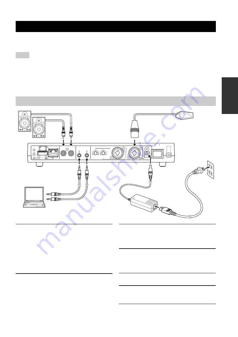
1
Connect a microphone to MIC LINE
INPUT.
y
•
You can use a XLR-type microphone or PHONE-type
microphone.
•
You can connect two microphones directly to this unit.
If you use only one microphone, connect it to IN1.
2
Connect speakers with built-in amplifier
to LINE OUTPUT.
3
Connect CONFERENCE IN of this unit to
the audio output jack of your PC or
videoconference system.
4
Connect CONFERENCE OUT of this unit
to the audio input jack of your PC or
videoconference system.
5
Connect the AC adapter to DC IN.
6
Connect the power cable to the AC
adapter.
7
Connect the power cable to an AC outlet.
Installation and Initial Setup
Notes
Connecting a microphone and speakers directly
R
L
LINE OUTPUT
OUT
IN
CONFERENCE
MIC/LINE INPUT
MIN
MAX
IN2
IN2
IN1
DC IN 12V
S
TANDBY ON
ETHER
DIP
S
W
AUTO
ANALYZER
INITIALIZE
PHANTOM
ACTIVE
ACTIVE
OFF
ON
LINE
MIC
MIN
MAX
IN1
ETHER
LINE
MIC
1
2
OFF
ON
PHANTOM
IN1 & 2
CONF.OUT
EC TYPE
MIX & F
S
DIP
S
W
S
ETTING
2
8
1
5
10
12
4
3
6
7
GAIN
13


