


8 - 12
–
+
ELEC
EBS01099
YES
NO
EBS01047
YES
NO
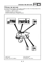
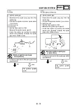
8. Source coil resistance
• Disconnect the C.D.I. magneto coupler
from the wire harness.
• Connect the pocket tester (
Ω
×
100) to the
source coil terminal.
Positive tester probe
→
black/red terminal
1
Negative tester probe
→
green/white terminal
2
• Measure the source coil resistance.
Source coil resistance
304 ~ 456
Ω
at 20 °C (68 °F)
(black/red and green/white)
Replace the pickup
coil/stator assembly.
9. Wiring
• Check the entire ignition system’s wiring.
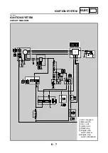
Refer to “CIRCUIT DIAGRAM”.
• Is the ignition system’s wiring properly
connected and without defects?
Replace the C.D.I.
unit.
Properly connect or
repair the ignition
system’s wiring.
G
/
W
W
/
L W
/
R
B
/
R
1
2
IGNITION SYSTEM
Summary of Contents for 5YF2-AE1
Page 1: ...YFM50S5YF2 AE1 SERVICE MANUAL ...
Page 2: ......
Page 8: ......
Page 9: ...GEN INFO 1 ...
Page 11: ...GEN INFO ...
Page 20: ...SPEC 2 ...
Page 22: ...SPEC ...
Page 44: ...2 22 SPEC OIL FLOW DIAGRAMS 1 Oil pump 2 Oil strainer ...
Page 53: ...CHK ADJ 3 ...
Page 55: ...CHK ADJ ...
Page 94: ...ENG 4 ...
Page 163: ...CARB 5 ...
Page 165: ...CARB ...
Page 172: ...DRIV 6 ...
Page 174: ...DRIV ...
Page 188: ......
Page 189: ...CHAS 7 ...
Page 220: ...ELEC 8 ...
Page 222: ... ELEC ...
Page 250: ......
Page 251: ...TRBL SHTG 9 ...
Page 253: ...TRBL SHTG ...
Page 259: ......
Page 260: ......
Page 261: ...YAMAHA MOTOR CO LTD 2500 SHINGAI IWATA SHIZUOKA JAPAN ...