


4 - 17
ENG
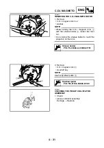
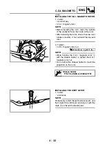
CAMSHAFT, ROCKER ARMS AND VALVES
EBS00240
CHECKING THE VALVES AND VALVE
SPRINGS
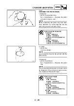
1. Measure:
• stem-to-guide clearance
Out of specification
→
Replace the valve
guide.
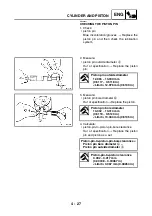
2. Replace:
• valve guide
▼▼▼
▼
▼ ▼▼▼
▼
▼ ▼▼▼
▼
▼ ▼▼▼
▼
▼ ▼▼▼
▼
▼ ▼▼▼
▼
▼▼▼
NOTE:
_
To ease guide removal, installation and to
maintain correct fit, heat the cylinder head to
100 °C (212 °F) in an oven.
a. Remove the valve guide using a valve guide
remover
1
.
b. Install the new valve guide using a valve
guide remover
1
and valve guide installer
2
.
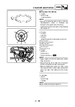
c. After installing the valve guide, bore the
valve guide using a valve guide reamer
3
to obtain proper stem-to-guide clearance.
NOTE:
_
After replacing the valve guide reface the valve
seat.
▲▲▲
▲
▲ ▲▲▲
▲
▲ ▲▲▲
▲
▲ ▲▲▲
▲
▲ ▲▲▲
▲
▲ ▲▲▲
▲
▲▲▲
Stem-to-guide clearance =
valve guide inside diameter
a
–
valve stem diameter
b
Stem-to-guide clearance
Intake
0.010 ~ 0.037 mm
(0.0004 ~ 0.0015 in)
<Limit>: 0.08 mm (0.0031 in)
Exhaust
0.025 ~ 0.052 mm
(0.0010 ~ 0.0020 in)
<Limit>: 0.10 mm (0.0039 in)
Valve guide remover (5 mm)
P/N. YM-04097, 90890-04097
Valve guide installer (5 mm)
P/N. YM-04098, 90890-04098
Valve guide reamer (5 mm)
P/N. 90890-04099
Summary of Contents for 5YF2-AE1
Page 1: ...YFM50S5YF2 AE1 SERVICE MANUAL ...
Page 2: ......
Page 8: ......
Page 9: ...GEN INFO 1 ...
Page 11: ...GEN INFO ...
Page 20: ...SPEC 2 ...
Page 22: ...SPEC ...
Page 44: ...2 22 SPEC OIL FLOW DIAGRAMS 1 Oil pump 2 Oil strainer ...
Page 53: ...CHK ADJ 3 ...
Page 55: ...CHK ADJ ...
Page 94: ...ENG 4 ...
Page 163: ...CARB 5 ...
Page 165: ...CARB ...
Page 172: ...DRIV 6 ...
Page 174: ...DRIV ...
Page 188: ......
Page 189: ...CHAS 7 ...
Page 220: ...ELEC 8 ...
Page 222: ... ELEC ...
Page 250: ......
Page 251: ...TRBL SHTG 9 ...
Page 253: ...TRBL SHTG ...
Page 259: ......
Page 260: ......
Page 261: ...YAMAHA MOTOR CO LTD 2500 SHINGAI IWATA SHIZUOKA JAPAN ...