ABS (ANTI-LOCK BRAKE SYSTEM)
4-70
EAS59C2401
REMOVING THE HYDRAULIC UNIT ASSEM-
BLY
ECA4B56013
Unless necessary, avoid removing and
installing the brake pipes of the hydraulic
unit assembly.
WARNING
EWA13930
Refill with the same type of brake fluid that
is already in the system. Mixing fluids may
result in a harmful chemical reaction, lead-
ing to poor braking performance.
ECA4B56014
• Handle the ABS components with care,
since they have been accurately adjusted.
Keep them away from dirt and do not sub-
ject them to shocks.
• Do not set the main switch to “ON” when
removing the hydraulic unit assembly.
• Do not clean with compressed air.
• Do not reuse the brake fluid.
• Brake fluid may damage painted surfaces
and plastic parts. Therefore, always clean
up any spilt brake fluid immediately.
• Do not allow any brake fluid to contact the
couplers. Brake fluid may damage the
couplers and cause bad contacts.
• If the brake hose flare nuts and union
bolts for the hydraulic unit assembly have
been removed, be sure to tighten them to
the specified torque and bleed the brake
system.
1. Remove:
• Brake hoses
• Rear brake pipe/joint assembly
TIP
Do not operate the brake levers while remov-
ing the brake hoses and rear brake pipe/joint
assembly.
ECA59C2412
When removing the brake hoses and rear
brake pipe/joint assembly, cover the area
around the hydraulic unit assembly to
catch any spilt brake fluid. Do not allow the
brake fluid to contact other parts.
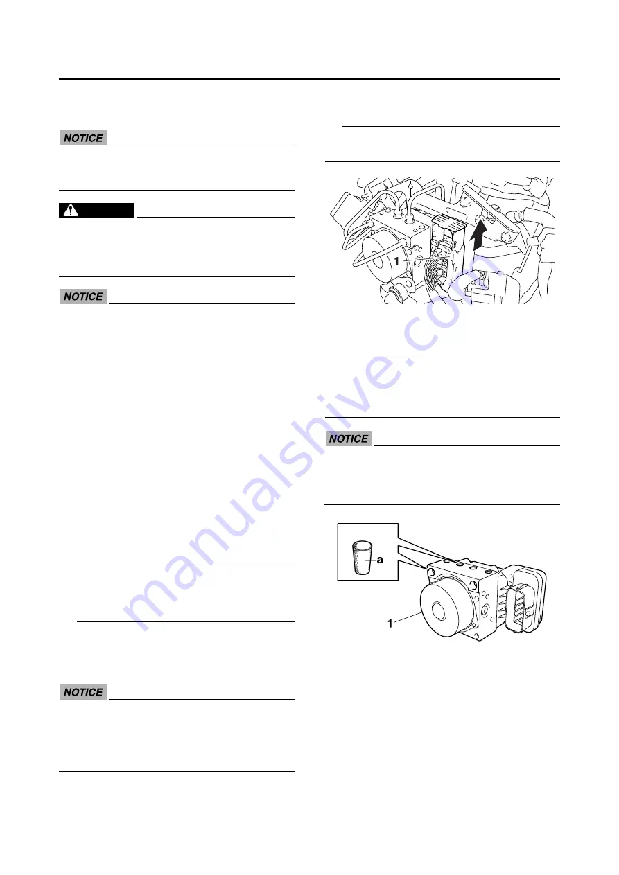
2. Disconnect:
• ABS ECU coupler “1”
TIP
Pull up the coupler ejection slider to discon-
nect the ABS ECU coupler.
3. Remove:
• Hydraulic unit assembly “1”
TIP
To avoid brake fluid leakage and to prevent for-
eign materials from entering the hydraulic unit
assembly, insert a rubber plug “a” or a bolt
(M10
×
1.0) into each flare nut hole.
ECA17300
When using a bolt, do not tighten the bolt
until the bolt head touches the hydraulic
unit. Otherwise, the brake pipe seating sur-
face could be deformed.
EAS59C2402
CHECKING THE HYDRAULIC UNIT ASSEM-
BLY
1. Check:
• Hydraulic unit assembly
Cracks/damage
→
Replace the hydraulic
unit assembly and the brake pipes that
are connected to the assembly as a set.
Summary of Contents for 2012 TMAX XP500A
Page 1: ...SERVICE MANUAL XP500A 2012 59C 28197 E1 ...
Page 6: ......
Page 8: ......
Page 54: ...SPECIAL TOOLS 1 45 ...
Page 79: ...LUBRICATION POINTS AND LUBRICANT TYPES 2 24 ...
Page 82: ...LUBRICATION SYSTEM CHART AND DIAGRAMS 2 27 EAS20410 LUBRICATION DIAGRAMS ...
Page 84: ...LUBRICATION SYSTEM CHART AND DIAGRAMS 2 29 ...
Page 86: ...LUBRICATION SYSTEM CHART AND DIAGRAMS 2 31 ...
Page 88: ...LUBRICATION SYSTEM CHART AND DIAGRAMS 2 33 ...
Page 90: ...COOLING SYSTEM DIAGRAMS 2 35 EAS20420 COOLING SYSTEM DIAGRAMS ...
Page 92: ...COOLING SYSTEM DIAGRAMS 2 37 ...
Page 94: ...CABLE ROUTING 2 39 EAS20430 CABLE ROUTING Handlebar top side view ...
Page 96: ...CABLE ROUTING 2 41 Handlebar front side and left side view ...
Page 98: ...CABLE ROUTING 2 43 Front brake front side and left side view ...
Page 100: ...CABLE ROUTING 2 45 Frame front side view ...
Page 102: ...CABLE ROUTING 2 47 Frame left side view ...
Page 104: ...CABLE ROUTING 2 49 Frame right side view ...
Page 106: ...CABLE ROUTING 2 51 Rear frame top side and right side view ...
Page 108: ...CABLE ROUTING 2 53 Rear brake top side and left side view ...
Page 110: ...CABLE ROUTING 2 55 Throttle body left side view ...
Page 112: ...CABLE ROUTING 2 57 Fuel tank top side left side and right side view ...
Page 114: ...CABLE ROUTING 2 59 Hydraulic unit top side and front side view ...
Page 116: ...CABLE ROUTING 2 61 ...
Page 119: ......
Page 154: ...PERIODIC MAINTENANCE 3 35 ...
Page 258: ...SWINGARM 4 101 ...
Page 329: ...OIL PUMP 5 68 ECA13890 After tightening the bolts make sure the oil pump turns smoothly ...
Page 346: ...TRANSMISSION 5 85 ...
Page 371: ...THROTTLE BODY 7 10 Throttle position sensor screw 3 5 Nm 0 35 m kgf 2 5 ft lbf ...
Page 372: ...THROTTLE BODY 7 11 ...
Page 375: ......
Page 376: ...IGNITION SYSTEM 8 1 EAS27090 IGNITION SYSTEM EAS27110 CIRCUIT DIAGRAM ...
Page 380: ...ELECTRIC STARTING SYSTEM 8 5 EAS27160 ELECTRIC STARTING SYSTEM EAS27170 CIRCUIT DIAGRAM ...
Page 386: ...CHARGING SYSTEM 8 11 EAS27200 CHARGING SYSTEM EAS27210 CIRCUIT DIAGRAM ...
Page 389: ...CHARGING SYSTEM 8 14 ...
Page 390: ...LIGHTING SYSTEM 8 15 EAS27240 LIGHTING SYSTEM EAS27250 CIRCUIT DIAGRAM ...
Page 394: ...SIGNALING SYSTEM 8 19 EAS27270 SIGNALING SYSTEM EAS27280 CIRCUIT DIAGRAM ...
Page 399: ...SIGNALING SYSTEM 8 24 ...
Page 400: ...COOLING SYSTEM 8 25 EAS27300 COOLING SYSTEM EAS27310 CIRCUIT DIAGRAM ...
Page 404: ...FUEL INJECTION SYSTEM 8 29 EAS27331 FUEL INJECTION SYSTEM EAS27340 CIRCUIT DIAGRAM ...
Page 445: ...FUEL INJECTION SYSTEM 8 70 ...
Page 446: ...FUEL PUMP SYSTEM 8 71 EAS27550 FUEL PUMP SYSTEM EAS27560 CIRCUIT DIAGRAM ...
Page 449: ...FUEL PUMP SYSTEM 8 74 ...
Page 450: ...IMMOBILIZER SYSTEM 8 75 EAS27640 IMMOBILIZER SYSTEM EAS27650 CIRCUIT DIAGRAM ...
Page 459: ...IMMOBILIZER SYSTEM 8 84 ...
Page 460: ...ABS ANTI LOCK BRAKE SYSTEM 8 85 EAS28790 ABS ANTI LOCK BRAKE SYSTEM EAS27730 CIRCUIT DIAGRAM ...
Page 462: ...ABS ANTI LOCK BRAKE SYSTEM 8 87 EAS27740 ABS COMPONENTS CHART ...
Page 464: ...ABS ANTI LOCK BRAKE SYSTEM 8 89 EAS27750 ABS COUPLER LOCATION CHART ...
Page 468: ...ABS ANTI LOCK BRAKE SYSTEM 8 93 EAS27810 BASIC PROCESS FOR TROUBLESHOOTING ...
Page 493: ...ABS ANTI LOCK BRAKE SYSTEM 8 118 ...
Page 494: ...ELECTRICAL COMPONENTS 8 119 EAS27973 ELECTRICAL COMPONENTS ...
Page 496: ...ELECTRICAL COMPONENTS 8 121 ...
Page 498: ...ELECTRICAL COMPONENTS 8 123 EAS27981 CHECKING THE SWITCHES ...
Page 527: ......
Page 528: ......


