31
Tyros2
NITOR SPEAKER
RS-MS02
ER’S MANUAL
ENUNGSANLEITUNG
E D’EMPLOI
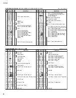
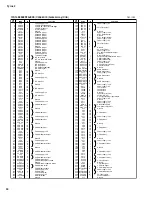
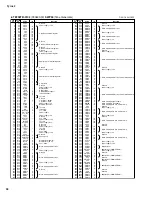
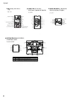
PIN
NO.
I/O
FUNCTION
NAME
PIN
NO.
I/O
FUNCTION
NAME
1
2
3
4
5
6
7
8
9
10
11
12
13
14
15
16
17
18
19
20
21
LB12
LB11
LB10
LB09
LB08
LB07
LB06
LB05
LB04
LB03
LB02
LB01
LB00
NC
NC
NC
RESET
CNVSS
XOUT
XIN
VSS
I/O
I/O
I/O
I/O
I/O
I/O
I/O
I/O
I/O
I/O
I/O
I/O
I/O
I/O
-
O
I
-
4-bit I/O port P1
1-bit I/O port D
Input is examined by skip decision.
CNTR0
CNTR1
4-bit I/O port P5
Not used
Reset input /output
Connect CNVss to Vss and apply "L"(0V)
to CNCss certainly.
Main clock output
Main clock input
Ground
22
23
24
25
26
27
28
29
30
31
32
33
34
35
36
37
38
39
40
41
42
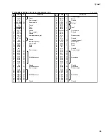
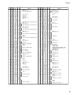
VDD
VDCE
L0
L1
L2
L3
L4
NC
NC
NC
D0
D1
D2
D3
LB19
LB18
LB17
LB16
LB15
LB14
LB13
-
I
I/O
I/O
I/O
I/O
I/O
I/O
I/O
I/O
I/O
I/O
I/O
I/O
I/O
I/O
I/O
I/O
Power supply
Voltage drop detection circuit enable
INT0
INT1
4-bit I/O port P3
4-bit I/O port P6
AIN0
Not used
AIN4
4-bit I/O port P4
AIN5
AIN6
AIN7
4-bit I/O port P0
4-bit I/O port P1
M34519M6-521FP
(X5646200)
CPU
(LSC)
Analog input
Interrupt input
Timer input/output
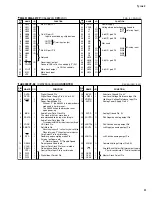
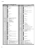
PIN
No.
NAME
I/O
FUNCTION
PIN
No.
NAME
I/O
FUNCTION
1
2
3
4
5
6
7
8
9
10
11
12
13
14
DVSS
DVDD
MCLK
PD
BICK
SDATA
LRCK
SMUTE
CS
DFS
DEM0
CCLK
DEM1
CDTI
DIF0
DIF1
DIF2
-
-
I
I
I
I
I
I
I
I
I
I
I
I
I
I
I
Digital Ground Pin
Digital Power Supply Pin, 3.3V or 5.0V
Master Clock Input Pin
Power-Down Mode Pin
When at "L",the Ak4393 is in power-down
mode and is held in reset.
The AK4393 should always be reset
upon power-up.
Audio Serial Data Clock Pin
The clock of 64fs or more than is
recommended to be input on this pin.
Audio Serial Data Input Pin
2's complement MSB-first data is input on this pin.
L/R Clock Pin
Soft Mute Pin
When this pin goes "H", soft mute cycle is initiated.
When returning "L",the output mute releases.
Chip Select Pin in serial mode
Doubla speed sampling mode Pin
(Internal pull-down pin)
"L":Normal Speed, "H":Double Speed
De-emphasis Enable pin
Control Data Clock Pin in serial mode
De-emphasis Enable pin
Control Data Input Pin in serial mode
Digital Input Format Pin
15
16
17
18
19
20
21
22
23
24
25
26
27
28
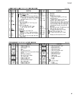
BVSS
VREFL
VREFH
AVDD
AVSS
AOUTR-
AOUTR+
AOUTL-
AOUTL+
VCOM
P/S
CKS0
CKS1
CKS2
I
I
-
-
O
O
O
O
O
O
I
I
I
I
Substrate Ground Pin, 0V
Low Level Voltage Reference Input Pin
High Level Voltage Reference Input Pin
Analog Power Supply Pin,5V
Analog Ground Pin, 0V
Rch Negative analog output Pin
Rch Positive analog output Pin
Lch Negative analog output Pin
Lch Positive analog output Pin
Common Voltage Output Pin,2.6V
Parallel/Serial Select Pin(Internal pull-up pin)
"L":Serial control mode,"H": Parallel control mode
Master Clock Select Pin
AK4393VF-E2
(XW029A00)
D/A CONVERTER


