16
Tyros2
MO
TR
OWNE
BEDIE
MODE
5-A. 2.5" HDD (Option)
(Time required: About 1 minute)
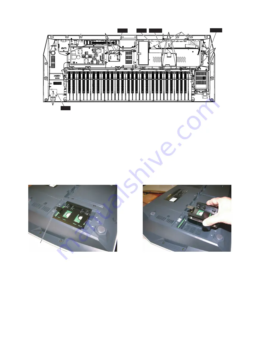
5-A-1 Remove the four (4) screws marked [100A]. The HDD
cover can then be removed. (Fig.1)
5-A-2 Remove the screw marked [100B]. The HDD with the
support can then be removed. (Fig.5A, Fig.5B)
HDSB
DJK
[530F] [530E]
[530G]
HP
CK
[530H]
Power Supply Unit
[530H]
DAC2A
[530]: Bind Head Tapping Screw-B 3.0X8 MFZN2Y (EP600250)
[530]: Bind Head Tapping Screw-B 3.0X8 MFZN2W3 (WE774300)
(Fig.5)
(Fig.5A)
(Fig.5B)
5-B. HDSB Circuit Board
(Time required: About 4 minutes)
5-B-1 Separate the unit into the upper case assembly and the
lower case assembly. (See procedure 1.)
5-B-2 In case that the HDD has been installed, remove the
HDD first. (See procedure 5-A.)
5-B-3 Remove the four (4) screws marked [530G]. The HDSB
circuit board can then be removed. (Fig.5)
[100B]


