23
Tyros2
NITOR SPEAKER
RS-MS02
ER’S MANUAL
ENUNGSANLEITUNG
E D’EMPLOI
Gear
Hing
Hing
LCD Lower Case
[180A]
[180B]
(Fig.20)
[180] Hinge
LCD Lower Case
Hinge [180]
(Fig.21)
LCD
LCD Upper Case
[190A]
[190C]
[190B]
LCL
LCR
(Fig.22)
[180]: Bind Head Tapping Screw-B 3.0X12 MFZN2B3 (WE998100)
[180]: Bind Head Tapping Screw-B 3.0X12 MFZN2B3 (WE998100)
[190]: Bind Head Tapping Screw-B 3.0X8 MFZN2W3 (WE774300)
27.
Disassembling the LCD Panel Assembly
27a. Gear (Time required: About 7 minutes)
27a-1 Remove the LCD panel assembly. (See procedure 26.)
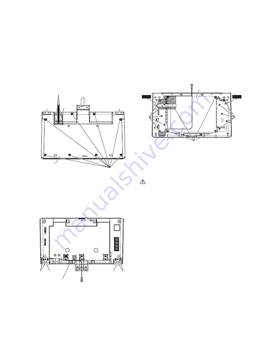
27a-2 Remove the four (4) screws marked [180A]. The gear
can then be removed. (Fig.20)
27b. Hinge (Time required: About 7 minutes)
27b-1 Remove the LCD panel assembly. (See procedure 26.)
27b-2 Remove the eight (8) screws marked [180B]. The LCD
lower case can then be removed. (Fig.20)
27b-3 Remove the two (2) screws marked [180] . The hinges
can then be removed. (Fig.21)
27c. LCL Circuit Board
(Time required: About 12 minutes)
27c-1 Remove the LCD panel assembly. (See procedure 26.)
27c-2 Remove the LCD lower case. (See procedure 27b-2.)
27c-3 Remove the five (5) screws marked [190A]. The LCL
circuit board can then be removed. (Fig.22)
*
When removing the FFC cable connected to
CN1,CN2,CN3 and CN4, release the lock of the connec-
tor first.
Also, after connecting it, do not forget to lock it.
27d. LCR Circuit Board
(Time required: About 12 minutes)
There may be high voltage components. Make sure to
disassemble the components after turning the power
switch off.
27d-1 Remove the LCD panel assembly. (See procedure 26.)
27d-2 Remove the LCD lower case. (See procedure 27b-2.)
27d-3 Remove the five (5) screws marked [190B]. The LCR
circuit board can then be removed. (Fig.22)
*
When removing the FFC cable connected to CN5, release
the lock of the connector first.
Also, after connecting it, do not forget to lock it.
27e LCD (Time required: About 12 minutes)
27e-1 Remove the LCD panel assembly. (See procedure 26.)
27e-2 Remove the LCD lower case. (See procedure 27b-2.)
27e-3 Remove the four (4) screws marked [190C]. The LCD
can then be removed. (Fig.22)


