13
Tyros2
NITOR SPEAKER
RS-MS02
ER’S MANUAL
ENUNGSANLEITUNG
E D’EMPLOI
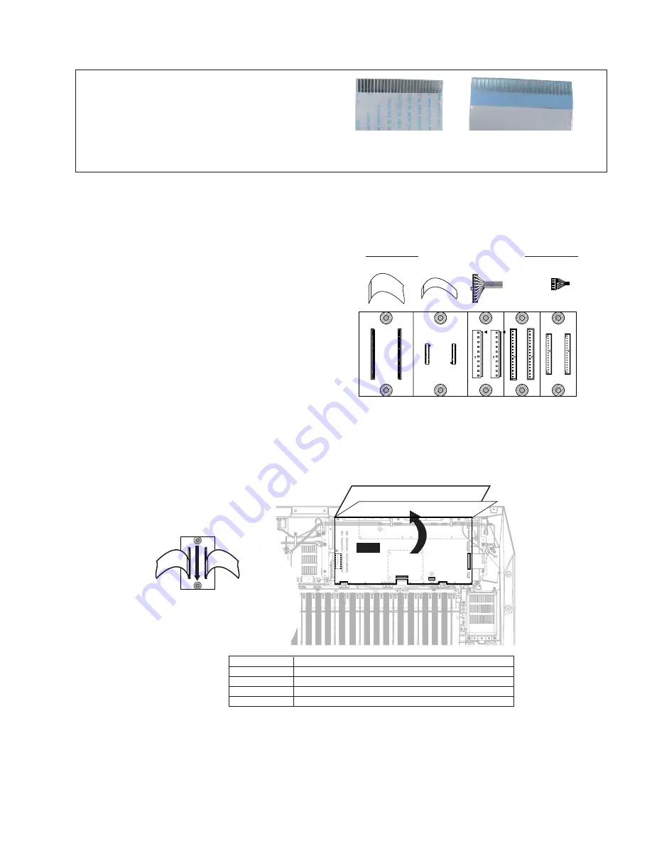
(Fig.A1)
(Fig.A3)
NOTES
•
When installing the unit, attach the filament tapes and the
cord binders as before.
•
Attention : Flat cable (FFC cable)
You can see the contact points from the back side.
Take care not to insert the flat cable into the connector in
the reverse direction. (Fig.A1)
Front surface
Back surface
Electrical Check After Disassembling
The DM circuit board is installed upside down, using
some screws.
Also, the DJK and DAC2A circuit boards are installed
under the DM circuit board.
When testing these circuit boards, you can perform the
electrical check by using a test sheet (X7275Z00) and
four connector assemblies supplied as service parts.
(Fig.A2)
The connection procedure is as follows.
A-1 Remove all the screws on the DM circuit board.
A-2 Extend the length of the original connector assem-
blies and the FFC cable by using the test sheet and
the connector assemblies as service parts.
Then, raise the DM circuit board vertically and
check it. (Fig.A3)
*
As for the number of pins of the connectors on the
test sheet, it is different from that of the original
cables.
When connecting each original cable to the test
sheet, connect the cable so that the edge of it can
match the edge of the connector. (Fig.A3)
DM
CN406 CN30
CN32
CN36
CONNECTOR
JIGS(Cable + Test Sheet)
CN30
VK112300 Connector As Test Sheet PH-16P
CN32
WE844400 Connector A Test Sheet FFC-40P
CN36
WE845800 Connector As Test Sheet VH-10P
CN406
WF761200 Connector As Test Sheet FFC-30P
Test Sheet
JIGS(Cable)
Original Cable
FFC-40P
FFC-30P
(WF761200)
(WE844400)
(VK112300)
(WE845800)
Test Sheet (X7275Z00)
VH-10P
Not Used
PH-16P
Connector Assembly, FFC Cable
(Fig.A2)


