MB1000 Peak Meter Bridge
375
DM1000 Version 2—Owner’s Manual
Appendix
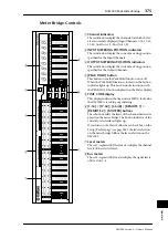
Meter Bridge Controls
A
Channel indicators
These indicators display the channels for which the lev-
els are currently displayed (Input Channels 1-16, 17-32,
33-48, Aux Outs 1-8, Bus Outs 1-8).
B
INPUT METERING POSITION indicators
These indicators display the current metering position
specified for the Input Channels.
C
OUTPUT METERING POSITION indicators
These indicators display the current metering position
specified for the Output Channels.
D
[PEAK HOLD] button
This button turns the Peak Hold function on or off.
When the Peak Hold function is turned on, the button
indicator lights up. This button works in unison with
the PEAK HOLD button displayed on the Meter display.
E
TIME CODE display
This display indicates the timecode or MIDI clock value
the DM1000 is receiving or generating.
F
[1-16] / [17-32] / [33-48] / [REMOTE 1] /
[REMOTE 2] / [MASTER] buttons
These buttons select the layers of the channel meters dis-
played on the meter bridge. The button indicator of the
currently-selected layer lights up.
If you turn on the Meter Follow Layer check box on the
Setup | Prefer1 page (see page 266), the layer selection
on the meter bridge follows the layer selection on the
DM1000.
G
Level meters
These 12-segment LED level meters display the channel
levels of the selected layer.
H
Bus meters
These 12-segment LED meters display the signal levels
of Bus Outs 1-8.
1-
1
6
MASTER
1
7-32
33-48
REMO
TE
1
REMO
TE
2
PE
AK
METE
R
BRIDGE
MB1000
FOR
TI
M
E
CO
DE
BE
A
T
CLO
CK
ME
A
SURE
HM
S
F
16
32
48
15
31
47
14
30
46
13
29
45
12
28
44
11
27
43
10
26
42
9
25
41
8
24
40
7
23
39
6
22
38
5
21
37
4
20
36
3
19
35
2
18
34
1
17
33
AU
X
8
AU
X
7
AU
X
6
AU
X
5
AU
X
4
AU
X
3
AU
X
2
AU
X
1
BU
S
8
BU
S
7
BU
S
6
BU
S
5
BU
S
4
BU
S
3
BU
S
2
BU
S
1
BU
S
8
BU
S
7
BU
S
6
BU
S
5
BU
S
4
BU
S
3
BU
S
2
BU
S
1
0
O
VER
-12
-15
-18
-24
-30
-36
-48
-3
-6
-9
0
O
VER
-12
-15
-18
-24
-30
-36
-48
-3
-6
-9
0
O
VER
-12
-15
-18
-24
-30
-36
-48
-3
-6
-9
0
O
VER
-12
-15
-18
-24
-30
-36
-48
-3
-6
-9
0
O
VER
-12
-15
-18
-24
-30
-36
-48
-3
-6
-9
INPUT METERING POSITION
OUTPUT METERING POSITION
PRE EQ
PRE F
ADER
POST F
ADER
PRE EQ
PRE F
ADER
POST F
ADER
PEAK HOLD
3
4
5
2
8
7
6
1
Summary of Contents for 006IPTO-F0
Page 42: ...42 Chapter 3 Operating Basics DM1000 Version 2 Owner s Manual ...
Page 52: ...52 Chapter 4 Connections and Setup DM1000 Version 2 Owner s Manual ...
Page 92: ...92 Chapter 7 Bus Outs DM1000 Version 2 Owner s Manual ...
Page 108: ...108 Chapter 8 Aux Sends DM1000 Version 2 Owner s Manual ...
Page 146: ...146 Chapter 11 Surround Functions DM1000 Version 2 Owner s Manual ...
Page 214: ...214 Chapter 16 Automix DM1000 Version 2 Owner s Manual ...
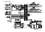
Page 385: ...DM1000 Block Diagram ...


