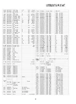
[C1053
C1054
C1055
C1056
C1057
C1058
C1059
C1060
C1061
C1062
C1063
C1064
C1065
C1066
C1067
C1068
C1069
C1070
C1071
C1072
C1073
C1074
C1075
C1076
C1077
C1078
C1091
C1092
C1093
C1094
TC1001
TC1002
L1002
L1003
L1004
L1005
L1006
L1007
L1008
L1009
L1010
L1011
L1013
L1014
L1015
CV1001
T1001
J1001
J1002
J1003
J1004
J1005
J1006
J1007
J1008
J1009
P1001
P1002
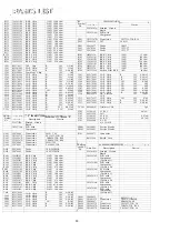
| Symbol
No.
—- —
Q401
Q402
Q403
D401
D402
X401
K22170223
K22170805
K40179006
K22170805
K22140807
K78100004
K78160001
K78120002
K22170817
K78160003
K22170235
K22170235
K22170235
K40129021
K40129008
K40179007
K22170805
K22170805
K22170805
K70147475
K40129012
K22170805
K22170805
K70127106
K22170805
K22170805
K22170203
K22170805
K22170817
K22170202
K91000167
K91000168
L0020900
L0020852
L0021290
L0021290
L1190194
L1690002
L0020917
L0021290
L0021290
L1190222
L0021290
L0021290
L2190001
L4020081
L0021558
P1090210
P1090210
P0090648
P0090647
P0090647
P1090602
P1090601
P0090640
P0090641
T9205642A
T9205638A
^^^1^^^^^^
J.U1 L 1'IU •
F2937101A
C029371AB
G1090859
G3316237F
G1090846
G2070003
G2070001
H0102858
CAP. Chip
CAP. Chip
AL. Electro.
CAP.
CAP. Chip
CAP. Chip
Tantalum. Chip
Tantalum. Chip
Tantalum. Chip
CAP. Chip
Tantalum. Chip
CAP. Chip
CAP. Chip
CAP. Chip
AL. Electro.
CAP.
AL. Electro.
CAP.
AL. Electro.
CAP.
CAP. Chip
CAP. Chip
CAP. Chip^
Tantalum CAP.
AL. Electro.
CAP.
CAP. Chip
CAP. Chip
Tantalum CAP.
CAP. Chip
CAP. Chip
CAP. Chip
CAP. Chip
CAP. Chip
CAP. Chip
Trimmer CAP.
Trimmer CAP.
Coil
•Coil
Coil
Coil
M. RFC
Coil. Chip
Coil
Coil
Coil
M. RFC
Coil
Coil
TOROID Coil
Helical Resonator
Coil
Connector
Connector
Connector
Connector
Connector
Connector
Connector
Connector
Connector
Wire-ASSY
Wire-ASSY
Printed Circuit
Board
PCB with
Component
1C ~
Transistor
1C
Diode
Diode
XTAL
CH 50V 33pF
B 50V O.OOluF
50V 2.2uF
B 50V O.OOluF
B 25V 0.022uF
10V lOuF
35V O.luF
16V 2.2uF
B 50V O.OluF
35V 0.22uF
CH 50V lOOpF
CH 50V lOOpF
CH 50V lOOpF
16V lOOOuF
16V 33uF
50V 3.3uF
B 50V O.OOluF
B 50V O.OOluF
B 50V O.OOluF
25V 4.7uF
16V lOuF
B 50V O.OOiuF
B 50V O.OOluF
16V lOuF
B 50V O.OOluF
B 50V O.OOluF
CH 50V 2pF
B 50V O.OOluF
B 50V O.OluF
CH ' 50V IpF
3pF
20pF
72uH
440MHz
44.3MHz
JP1001
Device
TK10487M
2SC1623-T2BL6
M5223FP
1SS226TE85R
1SS181TE85R
HC-49/T 44.545MHz
CD401
R401
R402
R403
R404
R405
R406
R407
R408
R409
R410
R411
R412
R413
R414
R415
R416
R417
R418
R419
R420
R421
R422
C401
C402
C403
C404
C405
C406
C407
C408
C409
C410
C411
C412
C413
C414
C415
C416
C417
C418
L401
TP401
-
•K^
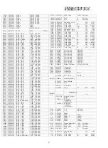
Symbol
No.
Q501
"^502
Q503
R501
R502
R503
R504
R505
R506
R507
R508
R509
R510
""R511
R512
R513
R514
"R515
R516
R517
R518
R519
R520
R521
R522
H7900180
J24205101
J24205101
J24205473
J24205471
J24205222
J24205102
J24205182
J24205332
J24205473
J24205223
J24205122
J24205474
J24205474
J24205222
J24205223
J24205683
J24205103
J24205122
J24205122
J24205103
J24205471
J24205223
K22170817
K22170805
K22170817
K22170805
K22170817
K22170219
K22141809
K22141809
K22170233
K22170817
K22141003
K22170801
K22170801
K22170801
K22170817
K22141809
K22170817
K22170227
L1190227
Q5000096
^,'„;'.; : .;
1
^.
^ CL1 L i'l U .
F2937102
C029372AB
G1090559
G1090831
G3316237F
G3070001
G3070001
G3070001
J24205472
J24205684
J24205472
J24205472
J24205682
J24205822
J24205684
J24205472
J24205472
J24205472
J24205333
J24205562
J24205225
J24205472
J24205154
J24205824
J24205823
J24205472
J24205224
J24205103
J24205102
J24205102
Ceramic DISC
RES. Chip
RES. Chip
RES. Chip
RES. Chip
RES. Chip
RES. Chip
RES. Chip
RES. Chip
RES. Chip
RES. Chip
RES. Chip
RES. Chip
RES. Chip
RES. Chip
RES. Chip
RES. Chip
RES. Chip
RES. Chip
RES. Chip
RES. Chip
RES. Chip
RES. Chip
CAP. Chip^
CAP. Chip
CAP. Chip
CAP. Chip
CAP. Chip
CAP. Chip^
CAP. Chip
CAP. Chip
CAP. Chip
CAP. Chip
CAP. Chip
CAP. Chip
CAP. Chip
CAP. Chip
CAP. Chip
CAP. Chip
CAP. Chip
CAP. Chip
M. RFC
Terminal
lOICUUirr
A-/C&L-1 A^J L1UI1
Printed Circuit
Board
PCB with
Component
1C
1C
Transistor
Transistor
Transistor
Transistor
RES. Chip
RES. Chip
RES. Chip
RES. Chip
RES. Chip
RES. Chip
RES. Chip
RES. Chip
RES. Chip
RES. Chip
RES. Chip
RES. Chip
RES. Chip
RES. Chip
RES. Chip
RES. Chip
RES. Chip
RES. Chip
RES. Chip
RES. Chip
RES. Chip
RES. Chip
CDB455C7
1/10W 100 ohm
I/10W 100 ohm
1/10W 47k ohm
1/10W 470 ohm
1/10W 22k ohm
1/10W 1k ohm
1/10W 1.8k ohm
1/10W 3.3k ohm
1/10W 47k ohm
1/10W 22k ohm
1/10W 1.2k ohm
1/10W 470k ohm
1/10W 470k ohm
1/10W 2.2k ohm
1/10W 22k ohm
1/10W 68k ohm
1/10W 10k ohm
1/10W 1.2k ohm
1/10W 1.2k ohm
1/10W 10k ohm
1/10W 470 ohm
JJ'10W 22k^hm
B 50V O.OluF
B 50V O.OOluF
B 50V O.OluF
B 50V O.OOluF
B 50V O.OluF
CH 50V 22pF
B 25V O.luF
B 25V O.luF
CH 50V 82pF
B 50V O.OluF
F 25V 0.047uF
B 50V 470pF
B 50V 470pF
B 50V 470pF
B 50V O.OluF
B 25V O.luF
B 50V O.OluF
CH 50V 47pF
0.33uH
fc -"'"' .•^--•"-^\
;
'? - •'. • '-.•
;
-' .
;
"^ -^v^T
LA6324M
UPD4052BG
2SC1623-T2BL6
FA1A4M-T2B
FA1A4M-T2B
FA1A4M-T2B
1/10W 4.7k ohm
1/10W 680k ohm
1/10W 4.7k ohm
1/10W 4.7k ohm
1/10W 6.8k ohm
1/10W 8.2k ohm
1/10W 680k ohm
1/1OW 4.7k ohm
1/10W 4.7k ohm
1/10W 4.7k ohm
1/10W 33k ohm
1/10W 5.6k ohm
1 / 1 0 W 2 . 2 M ohm
I / l O W 4.7k Ohm
1/10W 150k ohm
1/10W 820k ohm
1/10W 82k ohm • ;
1/10W 4.7k ohm
1/10W 220k ohm
1/10W lOk ohm
1/10W 1k ohm
1/10W 1k ohm
29
Summary of Contents for FT-712RH
Page 4: ...PA UNIT APC UNIT 430 VCO UNIT LCD UNIT CONTROL UNIT BOARD LAYOUT 2...
Page 8: ...reverse view of chip only side 6...
Page 9: ...MAIN UNIT VOLTAGE CHART DC VOLTS MAIN UNIT 1C VOLTAGE CHART DC VOLTS...
Page 15: ...20 32 HD404418A01F 02003 obverse view of 1C side 14...
Page 16: ...S obverse view of 1C side 15 ANODE 1 CATHOOE 1...
Page 17: ......
Page 18: ...PA UNIT No 7 XX obverse view of component side reverse view of component side 17...
Page 19: ...obverse view of chip only side reverse view of chip only side 18...
Page 20: ...19...
Page 21: ...MAIN UNIT 20...
Page 22: ...21 e s A...
Page 23: ...22...

