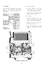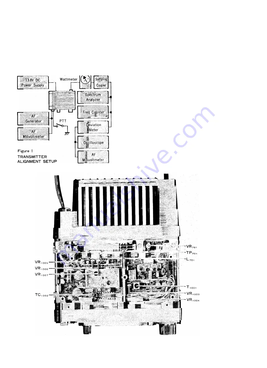
B. Transmitter
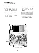
Set up the test equipment as shown in
Figure 1. Close the PTT line when making
adjustments. All adjustment points are on
the Main Unit.
1) Early Stage Coupling
a) Tune the transceiver to the center
of the band, and set the LOW
button to the high power position.
b) Adjust L701 for maximum power
output (at least 36 watts).
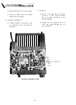
2) Power Output
a) With the transceiver tuned to the
center of the band, set the LOW
button to the high power position.
b) C o n n e c t the DC v o l t m e t e r to
TP701 on the PA Unit.
c) Press the PTT switch and adjust
VR701 for minimum on the volt-
meter.
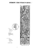
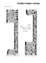
TRANSMITTER ALIGNMENT POINTS
25
Summary of Contents for FT-712RH
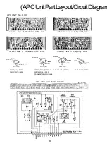
Page 4: ...PA UNIT APC UNIT 430 VCO UNIT LCD UNIT CONTROL UNIT BOARD LAYOUT 2...
Page 8: ...reverse view of chip only side 6...
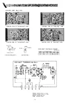
Page 9: ...MAIN UNIT VOLTAGE CHART DC VOLTS MAIN UNIT 1C VOLTAGE CHART DC VOLTS...
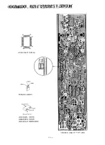
Page 15: ...20 32 HD404418A01F 02003 obverse view of 1C side 14...
Page 16: ...S obverse view of 1C side 15 ANODE 1 CATHOOE 1...
Page 17: ......
Page 18: ...PA UNIT No 7 XX obverse view of component side reverse view of component side 17...
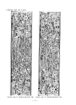
Page 19: ...obverse view of chip only side reverse view of chip only side 18...
Page 20: ...19...
Page 21: ...MAIN UNIT 20...
Page 22: ...21 e s A...
Page 23: ...22...

