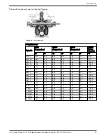
Pump size
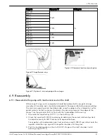
Dimension “A”
Packing size
8x6x12M
10.625
1/2
8x6x13
8x6x17
8x6x18
8x8x12
8x8x17
11.495
10x8x12
10x8x17
10x8x20
11.62
10x10x12
12.995
12x10x12
12x10x14
11.495
12x10x17
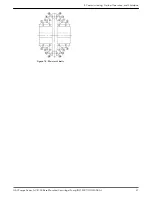
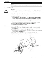
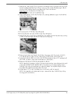
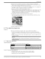
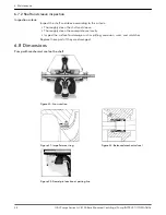
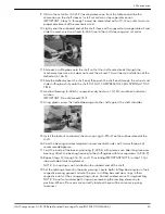
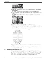
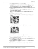
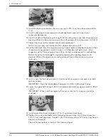
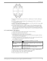
Figure 29: Impeller wear ring
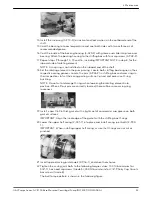
Figure 30: Dowel pin location at parting line
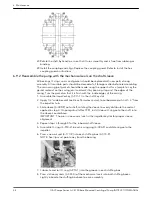
Figure 31: Optional — internal piping with seal cage
6.9 Reassembly
6.9.1 Reassemble the pump with mechanical seal on the shaft
All bearings, O-rings, seals, and gaskets should be replaced with new parts during
assembly. All reusable parts should be cleaned of all foreign matter before reassembling.
The main casing joint gasket should be made using the upper half as a template. Lay the
gasket material on the casing joint and mark it by pressing it against the edges of the
casing. Trim the gasket so that it is flush with the inside edges of the casing.
1. Assemble the impeller key (3–911–1) in the shaft key slot.
2. Check the impeller (4–002–0) and casing to determine the correct relationship. Heat
the impeller evenly to 300°F maximum to expand the bore.
For impellers with replaceable rings, heat each new ring (4–004–9) and slide it onto the
impeller. Hold the rings against the impeller shoulder until they cool.
3. Push the heated impeller on the shaft (3–007–0) against the shaft shoulder. Install
retaining ring (3–915–1).
6 Maintenance
G&L Pumps Series A-C 8100 Base Mounted Centrifugal Pump INSTRUCTION MANUAL
41

