• For optimal performance, the rear diff should be as free as possible, with
minimal slippage.
• When the front diff is looser than the rear diff, steering response
increases.
• When the front diff is tighter than the rear diff, steering response
decreases, but there is more stability in the turns.
• A tighter rear diff makes the car understeer slightly into corners, but
makes the car more difficult to control out of corners (powerslides).
• Make sure that neither diff slips under power; this causes power loss and
excessive wear.
• On very high traction surfaces, adjust diffs tighter for better response.
TIP: If you are not concerned about the weight of the
differential (rotating weight) but long life and low wear
are important for you, we strongly suggest using the XRAY
Spring Steel Differential #305001, which has the longest
life in the RC industry.
T
Tiig
gh
htte
en
niin
ng
g tth
he
e D
Diiffffe
erre
en
nttiia
allss
Tightening the differential reduces the amount of pulley slippage, but also
make for a heavier (harder) diff action. Adjust the diff until you have the
desired amount of slippage and diff action. An overly loose differential
may loosen off when running, which may ruin the differential. The
differential can be tightened when it is either in or out of the car.
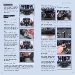
Insert a small Allen wrench into the aligned holes in the setscrew and long
diff shaft. Turn the long diff shaft 1/16 to 1/8 of a turn clockwise (CW) to
tighten. Remove the Allen wrench and recheck the diff.
LLo
oo
osse
en
niin
ng
g tth
he
e D
Diiffffe
erre
en
nttiia
allss
Loosening the differential increases the amount of pulley slippage, but also
make for a easier (lighter) diff action. Adjust the diff until you have the
desired amount of slippage and diff action. An overly tight diff will put
more pressure on the diff balls and bearings, which may ruin the
differential. The differential can be loosened when it is either in or out
of the car.
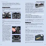
Insert a small Allen wrench into the aligned holes in the setscrew and long
diff shaft. Turn the long diff shaft 1/16 to 1/8 of a turn counter-clockwise
(CCW) to tighten. Remove the Allen wrench and recheck the diff.
B
Bu
uiilld
diin
ng
g tth
he
e D
Diiffffe
erre
en
nttiia
allss
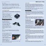
When you build the differential, do not tighten it fully initially; the
differential needs to be broken in properly. Tighten the diff very gently until
you feel some resistance. If you overtighten the diff initially, the diff balls
will mar the surface of the diff plates, damaging the diff balls and diff
plates. For exceptionally smooth operation and long diff life, use XRAY
Carbide Diff Balls #305091.
If you need to assemble/disassemble
the differentials, use needle-nose
pliers or circlip pliers to remove the
C-clip holding the axial bearing.
Final Adjustments
ROLLOUT
Rollout is a more precise way to set your car’s gearing because it takes into account tire
diameter, gear ratio, and transmission ratio. Rollout is defined as the distance a vehicle
moves forward per revolution of the motor. The car’s rollout changes as foam tire diameter
changes with tire wear, tire swap, and foam tire changes, even if you do not change your
gear ratio.
Rollout is affected by tire circumference. Calculate the tire circumference by doing the math:
Circumference = Tire diameter (in mm) x 3.14
If two cars have the same gear ratio, but one has larger diameter tires, that car will have a
larger rollout and higher top-end speed. Conversely, the car with smaller diameter tires will
have a smaller rollout and lower top-end speed. Note that using tires of different diameters
may also impact a car’s handling due to differences in clearance, tire squirm, and so on.
When setting up your car at a particular track and for a particular motor, we recommend
you speak with the local racers to see what a good rollout target number is. Try to match
the fastest racer’s rollout. Note that you cannot simply use the same pinion and spur
combination, as the tire diameter and transmission ratio may be different than the other
racer’s car. That’s when you want to consider rollout, in which the tire circumference and
transmission ratio are considered in addition to the spur/pinion ratio.
To calculate rollout, measure the circumference of the rear tire, determine the number of
teeth on the pinion and spur gears, and also the car’s transmission ratio (the T1 family has
a transmission ratio of 2.125). Then, plug those numbers into the following equations:
Rollout = Tire circumference
÷
final gear ratio
[where final gear ratio = (spur
÷
pinion) x transmission ratio]
Here is an example of rollout of an XRAY touring car using 58mm diameter foam tires.
Please note that if you run rubber tires (typically 63mm diameter), adjust the calculation
accordingly:
Transmission ratio = 2.125
Spur = 93T (48P)
Pinion = 24T (48P)
Tire diameter = 58mm
Tire circumference = 58mm x 3.14 = 182.12
Final gear ratio = (93 / 24) x 2.125 = 8.23
ROLLOUT = 182.12 / 8.23 = 22
Compare your car’s rollout with those of other racers’ cars. Now you have the option to
change your pinion or spur gears in order to get to the same rollout. You can also consider
changing the tire diameter. Remember that each change you make may have other impacts
on the performance of your car, so try to weigh all factors before making changes.
DIFFERENTIAL ADJUSTMENT
Differentials allow the wheels at opposite ends of the same axle to rotate at
different speeds. Why is this important? When a car turns in a circle, the
outer wheel has a larger diameter circle to follow than the inner wheel.
The outer wheel must travel further than the
inner wheel in the course of the circle, so it
needs to rotate faster to keep up. If the
differential is too tight, the result is that the
wheels "fight" each other for the proper rotation
speed; the result is a loss of traction.
Final Adjustments
5
6
Summary of Contents for T1R Raycer
Page 1: ......


