Xray T1R Raycer Set-Up Book Download Page 13

••  O

Ouutteerr  ppoossiittiioonn #

#33: More stable, less traction. 

••  M

Miiddddllee  ppoossiittiioonn #

#22: Optimum position for most tracks.

••  IInnnneerr  ppoossiittiioonn  #

#11: More traction, less stability.

Initial Setting:
Front camber link: Middle position #2

A

Ad

djju

ussttiin

ng

g  R

Re

ea

arr  C

Ca

am

mb

be

err

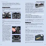
Adjust rear camber using the rear
upper camber link.

•• SShhoorrtteerr  lliinnkk:: More negative camber.

•• LLoonnggeerr lliinnkk:: Less negative camber.

Initial Setting:
Rear camber: -1.5° (tops of rear
wheels leaning inwards)

R

Re

ea

arr  C

Ca

am

mb

be

err  LLiin

nk

k  P

Po

ossiittiio

on

n

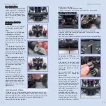
The position and length of the rear
camber link affects the car’s roll
center, which affects rear traction. In
general, the longer the link, the
more rear traction there is. The rear
uprights provide two camber link
positions. Switching from one
position to the other requires
lengthening or shortening of the
rear upper camber links to maintain
an appropriate driving camber
angle.

•• O

Ouutteerr  ppoossiittiioonn #

#22: More traction, less stability.

••  IInnnneerr  ppoossiittiioonn  #

#11: More stable, less traction.

Initial Setting:
Rear upper camber link: Inner position #1
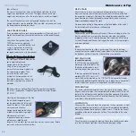
CASTER

Caster describes the angle of the 
C-hub block with respect to a line
perpendicular to the ground. Caster
angle affects on- and off-power
steering, as it will tilt the chassis
more or less depending on how
much caster is applied.

•• LLeessss  ccaasstteerr (more vertical):

Increases OFF-power steering
INTO a corner, but decreases
straight-line stability. 

•• M

Moorree  ccaasstteerr (more laid-down): Increases ON-power steering OUT OF a

corner, and increases straight-line stability, but makes the car harder to turn
into a corner. It also makes the car more stable through bumpy track
conditions.

Chassis Setup 

CAMBER

Camber is the angle of the wheels
relative to the ground when looked
at from the front or back.

•• N

Neeggaattiivvee   ccaam

mbbeerr:: The tire leans

inward at the top.

•• PPoossiittiivvee   ccaam

mbbeerr:: The tire leans

outward at the top.

Camber affects the car's traction. In general, more negative camber means
increased grip since the side-traction of the wheel increases. Do not use
more than -2.5° camber, and NEVER use positive camber.

The amount of front camber required
to maintain the maximum contact
patch largely depends on the amount
of caster. Higher degrees of caster
require little or no camber, while
lower degrees of caster require more
negative camber.

Perform these initial steps:
1.  Remove wheels.
2.  Put the car on the 
Hudy Set-Up System.
3. Press down the suspension of the
car a few times to let the suspension
settle.
A

Ad

djju

ussttiin

ng

g  F

Frro

on

ntt  C

Ca

am

mb

be

err

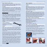
Adjust front camber using the front
upper camber link.

• SShhoorrtteerr  lliinnkk:: More negative
camber.
• LLoonnggeerr  lliinnkk:: Less negative camber.

Initial Setting:
Front camber: -1.0° (tops of front wheels
leaning inward)

F

Frro

on

ntt  C

Ca

am

mb

be

err  LLiin

nk

k  P

Po

ossiittiio

on

n

The position and length of the front
upper camber link affects the car’s
roll center, which affects front
traction. In general, the steeper the
angle of the camber link, the more
front traction there is. The front
shock tower provides three different
camber link positions, some of
which require lengthening or
shortening of the front upper
camber links to maintain an
appropriate driving camber angle. 

NOTE: Always use the same link positions on both sides of the car.

Chassis Setup 

23

CAMBER

+

-

1

1

2

3

2

CASTER

24

Summary of Contents for T1R Raycer

Page 1: ......

Page 2: ...l it can be difficult to apply this knowledge because of the inherent complexity in the setup process itself Your new T1R touring car with fully independent suspension was designed to have optimum per...

Page 3: ...ection servo reverse on the transmitter and re center the servo horn on the steering servo if necessary Next examine the car s servo saver Use the steering link adjustment between the servo horn and t...

Page 4: ...Rollout is a more precise way to set your car s gearing because it takes into account tire diameter gear ratio and transmission ratio Rollout is defined as the distance a vehicle moves forward per re...

Page 5: ...pulley to slip between the two outdrives C Ch he ec ck kiin ng g t th he e D Diif ff fe er re en nt tiia all A Ac ct tiio on n Remove the wrenches from the diff outdrive slots Hold the pulley stationa...

Page 6: ...PULLEY available option To be able to adjust the over steer under steer balance we suggest using the 305500 Main Layshaft With Adjustable One Way The one way pulley allows the front wheels to spin in...

Page 7: ...2 Final Adjustments S St tiif ff fe er r s sp pr riin ng gs s Makes the car more responsive The car reacts faster to steering inputs Stiff springs are suited for tight high traction tracks that aren t...

Page 8: ...helps control how quickly the shock compresses or rebounds L Le es ss s p piis st to on ns s o op pe en n Harder damping reacts like using thicker shock oil M Mo or re e p piis st to on ns s o op pe...

Page 9: ...bodies with a sloped nose A body with high downforce will provide higher traction through the turns However high downforce usually comes at the expense of drag so the car may not be the fastest on a l...

Page 10: ...k on the body to create more rear downforce Some wings even allow you to change their angle or use different canards side plates Most bodies typically come with a rear wing and some aftermarket wings...

Page 11: ...used to achieve better steering through the corners When setting up your steering it is very important that turning radii are the same when the car is turning either left or right Put the car on a Hud...

Page 12: ...anti dive the overall caster setting is 6 caster Chassis Setup When adjusting the steering servo adjust the steering so the steering blocks do not turn the maximum amount If they do decrease steering...

Page 13: ...s straight line stability but makes the car harder to turn into a corner It also makes the car more stable through bumpy track conditions Chassis Setup CAMBER Camber is the angle of the wheels relativ...

Page 14: ...er angle you must change the front C hub blocks to those with a different caster angle When changing the C hubs you must use left and right C hubs that have the same caster angle XRAY offers several d...

Page 15: ...and 4mm clips You can also use the 1mm clips but keep in mind that the sum of all clips used must always total 9mm L Le es ss s s sp pa ac ce er rs s iin n f fr ro on nt t o of f r re ea ar r a ar rm...

Page 16: ...ase then the anti roll bar needs to be adjusted 6 Make sure the wire is not tweaked If it is correct it by carefully bending it straight 7 If the wire is straight try to decrease or increase the heigh...

Page 17: ...anced car and has a tendency to pull to one side under acceleration or braking Tweak is caused by an uneven wheel load on one particular axle Now that the suspension geometry set up has been completed...

Page 18: ...all holes on the underside front and rear along the centerline To check the chassis left right balance place the two balance tools on a flat stable surface and then place the chassis on the tips of th...

Page 19: ...which should immediately be replaced Excess play indicates that a pivot pin holder is worn Check for the correct orientation of the plastic suspension holders They should be in the same direction SHOC...

Page 20: ...Be especially sure that the bearings in the steering blocks and rear uprights as well as the bearings supporting the ball diffs are perfectly clean and rotate freely Check all the bearings including t...

Reviews: