Xpelair Premier CF20 and Installation And Operating Instructions Manual Download Page 6

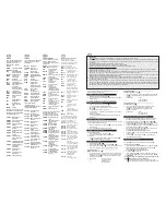
Ancillary Options

For speed and ease of

Installation, your installation may

require some of the Ancillaries

listed below:

WD100

Wall Duct

CFWG100

Wall Grille

FDA

Flat Duct Adaptor Kit

XCT100

Condensation Trap

DGW/B

Air Replacement Door

Grille

SP100

Spigot Plate

XAA

Air Brick Adaptor

VC10

Vent Cowl

WT10

Termination Ducting 

Kit

XF/FM

Flat Ducting 

(Plastic/Metal)

(Plastic 234 x 29mm

Metal 230 x 25mm)

VK10

Wall Vent Kit

FD100

Flexible Ducting

WDC5

Worm Drive Clips

XCMK

Ceiling Mounting Kit

XBP

In-Line Back Draught 

Shutter

EFT

Easy Fit Termination 

Kit

GMK

Glass Mounting Kit

PDXGF

Grease Filter

Listed below are some of the

spares available. See back  page

of this booklet for ordering details:
41520SK

Fixing kit (Entire kit)

41528SK

Circular Spigot (Entire

Range)

41731SK

Motor (DX200)

41733SK

Motor (CF20/CF20T/

DX200T)

41782SK

PCB Assy (DX200T)

41735SK

PCB Assy (CF20)

41736SK

PCB Assy (CF20T)

41737SK

Front Cover c/w Baffle

(DX200)

41738SK

Front Cover c/w Baffle

(DX200T)

41739SK

Front Cover c/w Baffle

(CF20/CF20T)

41740SK

Surround Moulding 

(Entire Range)

41741SK

Pull cord assembly 

(CF20/CF20T)

41742SK

Impeller (Entire 

Range)

Accessoires en option

Pour une installation rapide et

facile, il est préconisé de se munir

des accessoires figurant sur la

liste ci-dessous :
WD100 

Conduit mural

CFWG100 

Grille murale

FDA

Kit d'adapteur de 

conduit plat

XCT100 

Trappe de 

condensation 

DGW/B 

Grille de porte de 

remplacement d’air 

SP100 

Plaquette pour ergot

XAA

Adaptateur de brique 

perforée

VC10 

Capuchon d’évent 

WT10 

Kit de terminaison de 

conduit

XF/FM 

Conduit plat 

(Plastique/Métallique)

(Plastique 234 x 29 mm

Métallique 230 x 25 mm)

VK10 

Kit pour évent mural

FD100

Conduit flexible 

WDC5 

Colliers à serrage par 

vis sans fin

XCMK 

Kit pour montage au 

plafond

XBP

Obturateur de 

refoulement en 

ligne

EFT

Kit de terminaisons à 

encliqueter

GMK 

Kit de pose sur une 

vitre

PDXGF

Filtre de graisse

Liste de quelques pièces de

rechange : Pour la commande,

prière de se reporter à la dernière

page de cette notice : 

41520SK

Kit de fixation (Kit 

complet)

41528SK 

Ergot circulaire 

(gamme complète)

41731SK 

Moteur (DX200)

41733SK 

Moteur (CF20/CF20T/

DX200T)

41782SK 

Carte imprimée 

(DX200T)

41735SK 

Carte imprimée 

(CF20)

41736SK

Carte imprimée 

(CF20T)

41737SK 

Couvercle avant avec 

chicane (DX200)

41738SK 

Couvercle avant avec 

chicane (DX200T)

41739SK 

Couvercle avant avec 

chicane (CF20/CF20T)

41740SK 

Moulure de cadre 

(gamme complète)

41741SK 

Ens. interrupteur à 

cordon (CF20/CF20T)

41742SK 

Hélice (gamme 

complète)

Zubehör

Die unten aufgeführten Produkte

unterstützen eine schnelle und

problemlose Installation:
WD100

Wandrohr

CFWG100

Wandgitter

FDA

Flachrohr-Adapter

XCT100

Kondensationsfalle

DGW/B

Luftaustauschtürgitter

SP100

Zapfenplatte

XAA

Luftziegel-Adapter

VC10

Lüftungskappe

WT10

Bausatz für 

Rohrabbruch/ 

Rohrabschluss

XF/FM

Flachrohr 

(Kunststoff/Metall)

Kunststoff 234 x 29 mm,

Metall 230 x 25 mm

VK10

Bausatz für 

Wandlüftungs

FD100

Flexibles Rohr

WDC5

Schneckenantriebs-

klemmen

XCMK

Bausatz für 

Deckenmontage

XBP

In-Line-

Durchzugsklappe für 

die Rückseite

EFT

„Easy Fit" Bausatz für 

Rohrabbruch/ 

Rohrabschluss

GMK

Bausatz für 

Glasmontage

PDXGF

Fettfilter

Unten aufgeführt sind einige

Ersatzteile. Auf der Rückseite

dieses Hefts finden Sie

Einzelheiten über die Bestellung:
41520SK

Befestigungsbausatz 

(gesamter Bausatz)

41528SK

Rundzapfen 

(gesamtes Sortiment)

41731SK

Motor (DX200)

41733SK

Motor (CF20/CF20T/

DX200T)

41782SK

Flachbaugruppe 

(DX200T)

41735SK

Flachbaugruppe 

(CF20)

41736SK

Flachbaugruppe 

(CF20T)

41737SK

Frontabdeckung  C/W 

Ablenkung (DX200)

41738SK

Frontabdeckung C/W 

Ablenkung (DX200T)

41739SK

Frontabdeckung C/W 

Ablenkung (CF20/CF20T)

41740SK

Einfassungsform 

(gesamtes Sortiment)

41741SK

Zugschnur 

(CF20/CF20T)

41742SK

Gebläserad 

(gesamtes Sortiment)

Accessoireopties

Voor snelheid en gemak van

installatie is het mogelijk dat u

sommige van de onderstaande

accessoires nodig heeft.
WD100 

Muurdoorvoer

CFWG100 

Muurrooster

FDA

Adapterkit voor plat 

kanaal

XCT100 

Condensaatvanger

DGW/B 

Deurrooster voor 

luchtverversing

SP100 

Luchtinlaatplaat

XAA

Adapter voor 

gaatsteen

VC10 

Uitlaatkap

WT10 

Muurdoorvoerset

XF/FM 

Plat kanaal 

(plastic/metaal)

(Plastic 234 x 29mm

Metaal 230 x 25mm)

VK10 

Muuruitlaatset

FD100 

Flexibele slang

WDC5 

Schroefdraadklemmen

XCMK 

Plafondmontagekit

XBP

Gealigneerde 

achterste tochtklep

EFT 

Gemakkelijk te 

monteren aansluitingset

GMK 

Glasmontagekit

PDXGF

Oliefilter

Hieronder vindt u een lijst van

verkrijgbare reserveonderdelen.

Verwijs naar de achterste pagina

voor het bestellen ervan.
41520SK 

Montageset (volledig 

set)

41528SK 

Ronde luchtinlaat 

(volledige reeks)

41731SK 

Motor (DX200) **

41732SK 

Motor (DX200T) **

41733SK 

Motor (CF20/CF20T/

DX200T)

41734SK

PCB montage 

(DX200T)

41735SK 

PCB montage (CF20)

41736SK

PCB montage 

(CF20T)

41737SK

Bovendeel 

ventilatorhuis met 

schermplaat (DX200)

41738SK 

Bovendeel 

ventilatorhuis met 

schermplaat (DX200T)

41739SK 

Bovendeel 

ventilatorhuis met 

schermplaat 

(CF20/CF20T)

41740SK 

Lijstwerk voor 

montageplaat 

(volledige reeks)

41741SK 

Trekkoordmontage 

(CF20/CF20T)

41742SK 

Rotor (volledige 

reeks)

GB

F

D

NL

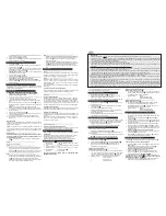
wooden frame into the internal wall and make good the hole.

2. Offer the fan box 

6

up to the wall. 

3. Screw the fan box 

6

to the wooden frame using the slots in the flange 

(screws not supplied).

If mounting in a ceiling (flush mounting)

1. The surround 

0

is not required. 

2. Insert the fan box 

6

into the hole and mark four positions using the slots in 

the flange 

B

.

3. Remove the fan box 

6

from ceiling and fit the four ceiling clips (supplied) 

over the edge of the hole, so that the clips align with the marks on the ceiling 

B

.

4. Drill 4 pilot holes into the ceiling through the hole of each clip, ensuring not to

damage the clip.

5. Fit the ducting to the circular spigot 

7

.

6. Offer the fan box 

6

up to the ceiling.

7. Slit the cable grommet. Pass the electrical cable into the fan box 

6

through

the front cable inlet hole.

Ensure cable grommet is in place and a tight fit.

8. Using the screws 

(Fig.

B

), fix the fan box flange to the ceiling clips.

Terminating the ducting

Fit an outer grille (such as CFWG100, not supplied in the DX200/DX200T) 

to the outer wall. For ceiling mounting, use appropriate ancillaries (not 

supplied).

Wire the electrical connections

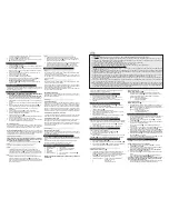
WARNING! THIS APPLIANCE MUST BE EARTHED

1. Isolate the electricity supply and remove all fuses.

The terminal block will accept cable up to 1.5mm

2

2. Use a double-pole isolating switch with a minimum contact gap of 3mm in 

both poles.

3. Use suitably rated 3-core or 4-core cable dependant on application.

4. Remove the retaining screws of the terminal cover, if still in position.

5. Wire the fan as shown in 

F

using the cable clamp provided. Check fan 

model to diagram.                                                                     

DX200: 

“LH” =Live (High Speed)/ “LL” = Live(Low Speed)

6. Replace the terminal cover 

5

and fasten the retaining screws.

7. See section on 

“User adjustments

” if you wish to use settings other than 

those that have been factory set.

8. Refit the front cover(Fig.

C

).

Connect the cable from the isolating switch to electrical supply wiring, and 

re-check installation.

10. Refit fuses before turning on electricity supply.

11. For fixed wiring circuits, the protective fuse for the appliance must not 

exceed 5A.

For Australia Only

CF20

– Connection to the supply - flexible 3-core cable with 3 pin plug top for

insertion into an approved 10A wall mounted surface switch with at least 3mm

clearance between contacts.

ALL OTHERS

– Permanently connected to the supply and a remote switch controls

operation. They should be directly wired to the supply through an approved 10A wall

mounted surface switch with at least 3mm clearance between contacts.

User adjustments   
Before making any adjustments, isolate the fan completely from the mains

supply, check specification below to see which features apply to your fan.

1. Remove the front cover and replace after adjustment (Fig. 

C

)

DX200

There are no user adjustments for this fan.

DX200T

1. The timer over-run period can be adjusted between approximately 30 

seconds and 20 minutes. Use an electrician’s screwdriver and turn screw “T”

(Fig.

D

), clockwise to increase time, anti-clockwise to decrease. (Factory 

preset to approximately 10 minutes)

CF20

1. The humidity setting is adjustable between approximately 50% and 90% 

relative humidity. Use an electrician’s screwdriver, and turn screw “RH” 

(Fig.

D

), clockwise to increase the relative humidity setting and anti-clockwise

to decrease. (Note: the fan is more sensitive at 50% RH than at 90% and is 

factory preset to approximately 70%).

CF20T

1. The timer over-run period can be adjusted between approximately 30 

seconds and 20 minutes. Use an electrician’s screwdriver and turn screw “T”

(Fig.

D

), clockwise to increase time, anti-clockwise to decrease. 

2. The humidity setting is adjustable between approximately 50% and 90% 

relative humidity. Use an electrician’s screwdriver, and turn screw “RH” 

(Fig.

D

), clockwise to increase the relative humidity setting and anti-clockwise

to decrease. (Note: the fan is more sensitive at 50% RH than at 90%).

Using the fan

DX200

Operate the fan using the external on/off switch. Repeat to switch off.

The fan speed is pre-set by the installer to either high or low speed.  (If a change

over switch has been installed then the user can switch between high speed and

low speed.)

DX200T

Operate the fan using the external on/off switch. Repeat to switch off. 

When the switch is turned off, the fan continues to operate for the selected over-

run timer period.  Top 

Light “I”

is lit when the external on/off switch is switched on.

The fan speed is pre-set by the installer to either high, medium or low speed.

Time delay start feature on or off

This is set by the installer to provide a 2-minute time delay start when the fan is

switched on using the external on/off switch.

CF20 / CF20T

Switched Operation

The fan can be wired with a separate on/off switch.  Fan operates at condensation

speed when switched on. Top 

“Light I”

is lit when the separate on/off switch is

switched on. When switched off, the fan will continue to operate if the humidity level

exceeds the set level. 

CF20T only

: When switched off, the fan continues to operate

at condensation speed for the adjustable timer over-run period.

Condensation Operation

The  fan  operates  at  condensation  control  speed,  when  the  relative  humidity

exceeds the set level, and turns off when the humidity drops. 

Boost Operation

The integral pull cord switch switches the fan to run at high speed.  Bottom 

“Light

II”

is lit when the fan is operating at high speed.

Note: If the separate on/off switch and integral pull cord are both on, then 

Lights “I”

and “II”

will both be lit and the fan will run at high speed.

CF20T only

Time delay start feature on or off

This is set by the installer to provide a 2-minute time delay start when the fan is

switched on using a separate on/off switch.

Cleaning

Before cleaning, isolate the fan completely from the mains supply

Only clean the external surface of the fan, using a damp lint free cloth.

Do not use strong detergents, solvents or chemical cleaners

Allow fan to dry thoroughly before use.

Apart from cleaning, no other maintenance is required.

Key  See Diagram 

E

1. Baffle Plate

2. Front Cover

3. Impeller

4. Fixing Screws

5. Terminal Cover

6. Fan Box

PLEASE LEAVE THIS LEAFLET WITH THE FAN FOR THE BENEFIT OF THE

USER

7. Circular Spigot

8. Clamp screws and wall plugs - 3 off

9. Fan Body Clamps – 3 off

10. Surround

11. Ceiling Screws 25mm long 4 off (Diagram 

B

)

12. Foam Tape

2.   A means for disconnection in all poles must be incorporated in the 

fixed wiring in accordance with the wiring regulations.

Summary of Contents for Premier CF20 and

Page 1: ...re reference ES Revision B Redring Xpelair Group Ltd Newcombe House Newcombe Way Orton Southgate Peterborough PE2 6SE England Redring Xpelair Group Ltd 567 2066 02 Revision C Guarantee UK This fan is guaranteed against defects for 3 years from the date of purchase Xpelair reserve the right to repair or replace the fan Keep your purchase receipt Any problems contact the address below Outside UK See...

Page 2: ...A B C D FIXING HOLE FIXING HOLE FRONT VIEW FIXING HOLE 66 222 93 66 94 20 213 252 20 182 40 62 56 ...

Page 3: ......

Page 4: ...de tornillo sin fin XCMK Kit de montaje en techo XBP Obturador de contratiro EFT Kit de terminación de fácil instalación GMK Kit de montaje de cristal PDXGF Filtro de grasa A continuación se listan algunos de los recambios disponibles Remítase a la última página de este folleto para los detalles de pedido 41520SK Kit de reparación kit completo 41528SK Tubo circular gama completa 41731SK Motor DX20...

Page 5: ...g ceiling joists and buried cables etc 2 Cut a 117mm diameter hole using the marked centre If installing in a ceiling flush mounting For 100mm diameter ducting 1 Mark a rectangular hole using the dimensions B 2 Cut the hole avoiding ceiling joists and buried cables etc For flat ducting This fan can be installed within a 47mm void without the circular spigot 7 Fig E Flat ducting adapter kit FDA ava...

Page 6: ...he clip 5 Fit the ducting to the circular spigot 7 6 Offer the fan box 6 up to the ceiling 7 Slit the cable grommet Pass the electrical cable into the fan box 6 through the front cable inlet hole Ensure cable grommet is in place and a tight fit 8 Using the screws Fig B fix the fan box flange to the ceiling clips Terminating the ducting Fit an outer grille such as CFWG100 not supplied in the DX200 ...

Page 7: ... trou de 117 mm de diamètre dans le mur extérieur en se servant du petit trou comme milieu 5 Mesurer l épaisseur du mur Couper le conduit du mur WD100 non fourni afin qu il ait une longueur de 64 mm de moins que l épaisseur du mur Pour un montage au plafond en surface Pour cette méthode il faut disposer d un espace au dessus du plafond ex comble ou grenier afin de prévoir l accès du conduit de 100...

Page 8: ...priés non fournis Raccorder les câbles électriques AVERTISSEMENT CET APPAREIL DOIT ÊTRE RACCORDÉ À LA TERRE 1 Isoler l alimentation électrique et retirer tous les fusibles La plaque à bornes peut recevoir un câble ayant un diamètre maximum de 1 5 mm2 2 Utiliser un sectionneur bipolaire présentant un entrefer de contact minimum de 3 mm dans les deux pôles 3 Utiliser un câble de tension nominale app...

Page 9: ...er entsprechenden nicht mitgelieferten Befestigung an der Decke Wandmontage Einsatz Die Einfassung 0 ist nicht erforderlich Montieren Sie das Rohr am Rundzapfen 7 Wenn die Größe des Loches den Empfehlungen entspricht 1 Befestigen Sie die drei Abzugskörperklemmen 9 am Abzugskasten 6 mit Hilfe von Schrauben 8 2 Schlitzen Sie die Durchgangstülle auf Schieben Sie nun die Kabel in den Abzugskasten 6 du...

Page 10: ...öhen und gegen den Uhrzeigersinn wenn Sie diese senken möchten Werkseinstellung etwa 10 Minuten CF20 2 Die Einstellung der Feuchtigkeit variiert etwa zwischen 50 und 90 relativer Feuchtigkeit Verwenden Sie einen Elektrikerschraubenzieher und drehen Sie die Schraube RH Abb D im Uhrzeigersinn wenn Sie die relative Feuchtigkeit erhöhen und gegen den Uhrzeigersinn wenn Sie diese senken möchten Bitte b...

Page 11: ... 8 of op het plafond met geschikte bevestigingsmiddelen niet bijgeleverd Als u de ventilator in een muur installeert verzonken U heeft de montageplaat 0 hier niet voor nodig Monteer het kanaal op de ronde luchtinlaat 7 Als het gat de aanbevolen afmetingen heeft 1 Monteer de drie montageklemmen 9 met schroeven 8 op het ventilatorhuis 6 2 Snijd de kabelring Schuif de elektrische kabels in het ventil...

Page 12: ...room hoge snelheid LL onder stroom lage snelheid 6 Plaats het kapje van het aansluitblok 5 terug en draai de overblijvende bevestigingsschroeven aan 7 Verwijs naar het onderdeel Afstellingen door de gebruiker voor het gebruik van standen die niet werden ingesteld in de fabriek 8 Plaats de schermplaat terug Fig C 9 Verbind de kabel vanuit de scheidingsschakelaar met de elektrische bedrading en cont...

Page 13: ... ILDSTED MÅ DET TAS FORHOLDSREGLER FOR Å UNNGÅ AT RØK BRENNGASSER STRØMMER TILBAKE I ROMMET FRA DEN ÅPNE AVTREKKSKANALEN TIL ILDSTEDET 9 FORSIKRE DEG OM AT ALLE RELEVANTE SIKKERHETSFORANSTALTNINGER ER TATT BRUK KORREKTE VERNEBRILLER OG VERNETØY OSV VED INSTALLERING OG VEDLIKEHOLD AV VIFTEN 10 FOR GENERELLE RETNINGSLINJER FOR PLASSERING AV VIFTEN SE FIG G INSTALLER ALLTID VIFTEN SÅ HØYT SOM MULIG 1...

Page 14: ...ttet med merkene B i himlingen 4 Bor 4 pilothull i himlingen gjennom hullet i hvert av klipsene uten å skade klipsene 5 Monter rørkanalen til den runde muffen 7 6 Anbring vifteboksen 6 i himlingen 7 Skjær hull i gummitetningen Før den elektriske kabelen inn i vifteboksen 6 gjennom det fremre kabelgjennomføringshullet Forsikre deg om at gummitetningen er på plass og sitter godt 8 Bruk skruene Fig B...

Page 15: ...do di avvio di 2 minuti quando l aspiratore viene acceso usando un interruttore acceso spento separato Pulizia Prima di pulire l aspiratore isolarlo completamente dalla rete elettrica Pulire solo la superficie esterna dell aspiratore con un panno umido che non sfilacci Non usare detergenti solventi o prodotti chimici aggressivi Lasciar asciugare completamente l aspiratore prima di riutilizzarlo Ol...

Page 16: ... fyra punkterna med hjälp av flänshålen B 3 Avlägsna fläktenheten 6 från taket och placera de fyra takklämmorna bifogas över hålets kant så att de överensstämmer med markeringarna i taket B 4 Borra fyra inledande hål i taket genom hålet i varje klämma Skada inte klämmorna 5 Montera fast trumman på mufförbindningen 7 6 Placera fläktenheten 6 på väggen 7 Öppna kabelringen För in elkabeln i fläktenhe...

Page 17: ... fyra punkterna med hjälp av flänshålen B 3 Avlägsna fläktenheten 6 från taket och placera de fyra takklämmorna bifogas över hålets kant så att de överensstämmer med markeringarna i taket B 4 Borra fyra inledande hål i taket genom hålet i varje klämma Skada inte klämmorna 5 Montera fast trumman på mufförbindningen 7 6 Placera fläktenheten 6 på väggen 7 Öppna kabelringen För in elkabeln i fläktenhe...

Page 18: ...do di avvio di 2 minuti quando l aspiratore viene acceso usando un interruttore acceso spento separato Pulizia Prima di pulire l aspiratore isolarlo completamente dalla rete elettrica Pulire solo la superficie esterna dell aspiratore con un panno umido che non sfilacci Non usare detergenti solventi o prodotti chimici aggressivi Lasciar asciugare completamente l aspiratore prima di riutilizzarlo Ol...

Page 19: ...ttet med merkene B i himlingen 4 Bor 4 pilothull i himlingen gjennom hullet i hvert av klipsene uten å skade klipsene 5 Monter rørkanalen til den runde muffen 7 6 Anbring vifteboksen 6 i himlingen 7 Skjær hull i gummitetningen Før den elektriske kabelen inn i vifteboksen 6 gjennom det fremre kabelgjennomføringshullet Forsikre deg om at gummitetningen er på plass og sitter godt 8 Bruk skruene Fig B...

Page 20: ... ILDSTED MÅ DET TAS FORHOLDSREGLER FOR Å UNNGÅ AT RØK BRENNGASSER STRØMMER TILBAKE I ROMMET FRA DEN ÅPNE AVTREKKSKANALEN TIL ILDSTEDET 9 FORSIKRE DEG OM AT ALLE RELEVANTE SIKKERHETSFORANSTALTNINGER ER TATT BRUK KORREKTE VERNEBRILLER OG VERNETØY OSV VED INSTALLERING OG VEDLIKEHOLD AV VIFTEN 10 FOR GENERELLE RETNINGSLINJER FOR PLASSERING AV VIFTEN SE FIG G INSTALLER ALLTID VIFTEN SÅ HØYT SOM MULIG 1...

Page 21: ...room hoge snelheid LL onder stroom lage snelheid 6 Plaats het kapje van het aansluitblok 5 terug en draai de overblijvende bevestigingsschroeven aan 7 Verwijs naar het onderdeel Afstellingen door de gebruiker voor het gebruik van standen die niet werden ingesteld in de fabriek 8 Plaats de schermplaat terug Fig C 9 Verbind de kabel vanuit de scheidingsschakelaar met de elektrische bedrading en cont...

Page 22: ... 8 of op het plafond met geschikte bevestigingsmiddelen niet bijgeleverd Als u de ventilator in een muur installeert verzonken U heeft de montageplaat 0 hier niet voor nodig Monteer het kanaal op de ronde luchtinlaat 7 Als het gat de aanbevolen afmetingen heeft 1 Monteer de drie montageklemmen 9 met schroeven 8 op het ventilatorhuis 6 2 Snijd de kabelring Schuif de elektrische kabels in het ventil...

Page 23: ...öhen und gegen den Uhrzeigersinn wenn Sie diese senken möchten Werkseinstellung etwa 10 Minuten CF20 2 Die Einstellung der Feuchtigkeit variiert etwa zwischen 50 und 90 relativer Feuchtigkeit Verwenden Sie einen Elektrikerschraubenzieher und drehen Sie die Schraube RH Abb D im Uhrzeigersinn wenn Sie die relative Feuchtigkeit erhöhen und gegen den Uhrzeigersinn wenn Sie diese senken möchten Bitte b...

Page 24: ...er entsprechenden nicht mitgelieferten Befestigung an der Decke Wandmontage Einsatz Die Einfassung 0 ist nicht erforderlich Montieren Sie das Rohr am Rundzapfen 7 Wenn die Größe des Loches den Empfehlungen entspricht 1 Befestigen Sie die drei Abzugskörperklemmen 9 am Abzugskasten 6 mit Hilfe von Schrauben 8 2 Schlitzen Sie die Durchgangstülle auf Schieben Sie nun die Kabel in den Abzugskasten 6 du...

Page 25: ...priés non fournis Raccorder les câbles électriques AVERTISSEMENT CET APPAREIL DOIT ÊTRE RACCORDÉ À LA TERRE 1 Isoler l alimentation électrique et retirer tous les fusibles La plaque à bornes peut recevoir un câble ayant un diamètre maximum de 1 5 mm2 2 Utiliser un sectionneur bipolaire présentant un entrefer de contact minimum de 3 mm dans les deux pôles 3 Utiliser un câble de tension nominale app...

Page 26: ... trou de 117 mm de diamètre dans le mur extérieur en se servant du petit trou comme milieu 5 Mesurer l épaisseur du mur Couper le conduit du mur WD100 non fourni afin qu il ait une longueur de 64 mm de moins que l épaisseur du mur Pour un montage au plafond en surface Pour cette méthode il faut disposer d un espace au dessus du plafond ex comble ou grenier afin de prévoir l accès du conduit de 100...

Page 27: ...he clip 5 Fit the ducting to the circular spigot 7 6 Offer the fan box 6 up to the ceiling 7 Slit the cable grommet Pass the electrical cable into the fan box 6 through the front cable inlet hole Ensure cable grommet is in place and a tight fit 8 Using the screws Fig B fix the fan box flange to the ceiling clips Terminating the ducting Fit an outer grille such as CFWG100 not supplied in the DX200 ...

Page 28: ...g ceiling joists and buried cables etc 2 Cut a 117mm diameter hole using the marked centre If installing in a ceiling flush mounting For 100mm diameter ducting 1 Mark a rectangular hole using the dimensions B 2 Cut the hole avoiding ceiling joists and buried cables etc For flat ducting This fan can be installed within a 47mm void without the circular spigot 7 Fig E Flat ducting adapter kit FDA ava...

Page 29: ...de tornillo sin fin XCMK Kit de montaje en techo XBP Obturador de contratiro EFT Kit de terminación de fácil instalación GMK Kit de montaje de cristal PDXGF Filtro de grasa A continuación se listan algunos de los recambios disponibles Remítase a la última página de este folleto para los detalles de pedido 41520SK Kit de reparación kit completo 41528SK Tubo circular gama completa 41731SK Motor DX20...

Page 30: ......

Page 31: ...A B C D FIXING HOLE FIXING HOLE FRONT VIEW FIXING HOLE 66 222 93 66 94 20 213 252 20 182 40 62 56 ...

Page 32: ... Free technical advice Help Desk from Engineers on all aspects of ventilation Free design service quotations and site surveys Outside UK See International section below Please ask for details on Tel 44 0 8709 000430 Fax 44 0 8709 000530 Also at the address below Head Office UK Sales Office and Spares Applied Energy Products Ltd Morley Way Peterborough PE2 9JJ England Tel 44 0 1733 456789 Fax 44 0 ...

Reviews: