


GB
This appliance is intended for
connection to fixed wiring.
Check that the electrical rating shown
on the appliance matches the mains
supply.
WARNING: THIS APPLIANCE MUST
BE EARTHED.
All installations must be supervised
by a qualified electrician.
Installation and wiring must conform
to current IEE regulations (UK), local
or appropriate regulations
(other countries).
If you have any queries before
installing these products or after they
have been installed, call the
Xpelair Technical H44 (0) 8709
000430. Our engineers are there to
help you during normal office
hours (UK only) and may be faxed at
all other times +44 (0) 8709 000530.
Customers outside the UK please
contact your local Xpelair distributor,
details of which are available
from the UK office.
The GX6 models have the following
features:
�
Window / wall / panel / roof mounting
options.
�
For remote switch operation.
�
Single speed extract operation.
�
Trickle ventilation setting.
�
Integral pull cord operation.
�
Single speed extract operation.
�
Trickle ventilation setting.
�
Integral pull cord operation.
�
Integral timer facility.
�
Single speed extract operation.
�
Trickle ventilation setting.
�
For remote switch operation.
�
Integral timer facility.
�
Single speed operation.
�
Trickle ventilation setting.
�
For remote switch operation.
�
Integral humidistat / timer facility.
�
Single speed operation.
�
Trickle ventilation setting.
�
For remote switch operation.
�
Integral pull cord operation.
�
Integral humidistat / timer facility.
�
Two speed operation.
�
Trickle ventilation setting.
�
Remote switch operation.
�
Single speed extract operation.
�
Solenoid operated back draught
shutters, for instant opening and
closing.
�
Trickle ventilation setting.
�
For remote switch operation.
�
Single speed extract operation.
�
Trickle ventilation setting.
�
IP25 ingress protection.
�
A
means for disconnection in all poles
m
ust be provided in the fixed wiring in
accordance with the wiring rules.
�
If metal switch boxes are used,
earthing regulations must be followed.
�
The GX6, GXC6, GXC6T and GXS6
require suitably rated 3-core cable
(see “Installing switches and cables”
section).
�
The GX6 (IP25) require suitably rated
circular 3-core cable with a diameter
not less than 5.5mm (see “Installing
switches and cables” section).
�
The GX6T, GX6HT and GX6HT2
require suitably rated 4 or 5 core
cable (see “Installing switches and
cables” section).
�
The GX6T, GX6HT and GX6HT2
requires a wall or ceiling mounted “on
/off’ switch with built-in indicator
light. For external boost/triggering,
two switches are required.
�
6mm blade large screwdriver, 3mm
blade electrician’s screwdriver and
No.1 & 2 Pozidriv screwdrivers.
�
A single glazed window with a
minimum glass thickness of 4mm or a
double glazed unit with a pre-
prepared sealed hole.
�
Masonry drill, hammer & chisel (or
core drill equipment, if available).
�
Mortar (to make good the hole).
�
Wall kit WK6/300 (available from
Xpelair) for walls up to 300mm (12”)
thick or WK6/450 (available from
Xpelair) for walls up to 450mm (18”)
thick.
Xpelair GX6, GX6 (IP25), GXC6,
GXC6T, GX6HT, GX6HT2 & GXS6
Installation and Operating Instructions
PLEASE LEAVE THIS LEAFLET WITH THE FAN, FOR THE BENEFIT
OF THE USER.
Installing the fan
Description
GX6
GXC6
GXC6T
GX6T
GX6HT
GX6HT2
GXS6
GX6 (IP25)
What the installer will need
If window mounting the fan, you
will also need:
If wall mounting the fan, you will
also need:
Where to locate the fan
�
4 mounting fasteners (use fasteners
suitable for wall type. Recommended
screw size for standard brick - No.8 x
38mm Pan Head).
�
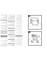
Locate it as high as possible.
�
At least 145mm from edge of the wall/
window frame to the hole centre (see
Fig. A.).
�
As far as possible from and opposite
to the main source of air replacement
to ensure airflow across the room
(eg, Opposite an internal doorway).
�
Near the source of steam or odours.
�
Not where ambient temperatures
are likely to exceed 50 degrees C.
�
If installed in a kitchen, fans must
not be mounted immediately above
a cooker hob or eye level grill.
�
If installing in a room containing a
fuel burning device, which has a
non balanced flue, it is the
installers responsibility to ensure
that there is enough replacement
air to prevent fumes being drawn
down the flue when the fan is
operating up to maximum extract.
Refer to Building Regulations for
specific requirements. Exhaust air
must not be discharged into a flue
used for exhausting fumes from
appliances supplied with energy
other than electric.
Requirements of all authorities
concerned must be observed for
exhaust air discharge and intake
flow rates.
�
When intended for use in possible
chemical corrosive atmospheres,
consult our technical service
department. (For overseas markets
contact your local Xpelair
Distributor).
�
This electrical product, if installed
in a shower room or bathroom,
must be situated so that it cannot
be touched by persons making use
of the bath or shower.
1.
Check that there are no buried
pipes or cables (eg. electricity, gas,
water) behind the switch location
(in the wall or above the ceiling).
2. Lay in the cable from the isolating
switch to the fan location via the on/
off switch (see Fig.E1), SW1 (see
Fig.E2.) and external boost SW1 (see
Fig.E3) if required.
3. Lay in the cable from the isolating
switch to the point of connection to
the mains supply.
WARNING: DO NOT MAKE ANY
CONNECTIONS TO THE ELEC-
TRICAL SUPPLY AT THIS STAGE.
4. Install the isolating switch and the on/
off switch (see Fig.E1), SW1 (see
Fig.E2) and external boost SW2
(see Fig.E3) if required.
5. Make all connections within the
isolating switch and the on/off switch
if required.
Note: When installed in a bathroom
all switches must be of a pull cord
type and must be situated so that
they cannot be touched by persons
making use of the bath or shower.
Installing the switches and
cables
GB
This appliance is intended for
connection to fixed wiring.
Check that the electrical rating shown
on the appliance matches the mains
supply.
WARNING: THIS APPLIANCE MUST
BE EARTHED.
All installations must be supervised
by a qualified electrician.
Installation and wiring must conform
to current IEE regulations (UK), local
or appropriate regulations
(other countries).
If you have any queries before
installing these products or after they
have been installed, call the
Xpelair Technical H44 (0) 8709
000430. Our engineers are there to
help you during normal office
hours (UK only) and may be faxed at
all other times +44 (0) 8709 000530.
Customers outside the UK please
contact your local Xpelair distributor,
details of which are available
from the UK office.
The GX6 models have the following
features:
�
Window / wall / panel / roof mounting
options.
�
For remote switch operation.
�
Single speed extract operation.
�
Trickle ventilation setting.
�
Integral pull cord operation.
�
Single speed extract operation.
�
Trickle ventilation setting.
�
Integral pull cord operation.
�
Integral timer facility.
�
Single speed extract operation.
�
Trickle ventilation setting.
�
For remote switch operation.
�
Integral timer facility.
�
Single speed operation.
�
Trickle ventilation setting.
�
For remote switch operation.
�
Integral humidistat / timer facility.
�
Single speed operation.
�
Trickle ventilation setting.
�
For remote switch operation.
�
Integral pull cord operation.
�
Integral humidistat / timer facility.
�
Two speed operation.
�
Trickle ventilation setting.
�
Remote switch operation.
�
Single speed extract operation.
�
Solenoid operated back draught
shutters, for instant opening and
closing.
�
Trickle ventilation setting.
�
For remote switch operation.
�
Single speed extract operation.
�
Trickle ventilation setting.
�
IP25 ingress protection.
�
A
means for disconnection in all poles
m
ust be provided in the fixed wiring in
accordance with the wiring rules.
�
If metal switch boxes are used,
earthing regulations must be followed.
�
The GX6, GXC6, GXC6T and GXS6
require suitably rated 3-core cable
(see “Installing switches and cables”
section).
�
The GX6 (IP25) require suitably rated
circular 3-core cable with a diameter
not less than 5.5mm (see “Installing
switches and cables” section).
�
The GX6T, GX6HT and GX6HT2
require suitably rated 4 or 5 core
cable (see “Installing switches and
cables” section).
�
The GX6T, GX6HT and GX6HT2
requires a wall or ceiling mounted “on
/off’ switch with built-in indicator
light. For external boost/triggering,
two switches are required.
�
6mm blade large screwdriver, 3mm
blade electrician’s screwdriver and
No.1 & 2 Pozidriv screwdrivers.
�
A single glazed window with a
minimum glass thickness of 4mm or a
double glazed unit with a pre-
prepared sealed hole.
�
Masonry drill, hammer & chisel (or
core drill equipment, if available).
�
Mortar (to make good the hole).
�
Wall kit WK6/300 (available from
Xpelair) for walls up to 300mm (12”)
thick or WK6/450 (available from
Xpelair) for walls up to 450mm (18”)
thick.
Xpelair GX6, GX6 (IP25), GXC6,
GXC6T, GX6HT, GX6HT2 & GXS6
Installation and Operating Instructions
PLEASE LEAVE THIS LEAFLET WITH THE FAN, FOR THE BENEFIT
OF THE USER.
Installing the fan
Description
GX6
GXC6
GXC6T
GX6T
GX6HT
GX6HT2
GXS6
GX6 (IP25)
What the installer will need
If window mounting the fan, you
will also need:
If wall mounting the fan, you will
also need:
Where to locate the fan
�
4 mounting fasteners (use fasteners
suitable for wall type. Recommended
screw size for standard brick - No.8 x
38mm Pan Head).
�
Locate it as high as possible.
�
At least 145mm from edge of the wall/
window frame to the hole centre (see
Fig. A.).
�
As far as possible from and opposite
to the main source of air replacement
to ensure airflow across the room
(eg, Opposite an internal doorway).
�
Near the source of steam or odours.
�
Not where ambient temperatures
are likely to exceed 50 degrees C.
�
If installed in a kitchen, fans must
not be mounted immediately above
a cooker hob or eye level grill.
�
If installing in a room containing a
fuel burning device, which has a
non balanced flue, it is the
installers responsibility to ensure
that there is enough replacement
air to prevent fumes being drawn
down the flue when the fan is
operating up to maximum extract.
Refer to Building Regulations for
specific requirements. Exhaust air
must not be discharged into a flue
used for exhausting fumes from
appliances supplied with energy
other than electric.
Requirements of all authorities
concerned must be observed for
exhaust air discharge and intake
flow rates.
�
When intended for use in possible
chemical corrosive atmospheres,
consult our technical service
department. (For overseas markets
contact your local Xpelair
Distributor).
�
This electrical product, if installed
in a shower room or bathroom,
must be situated so that it cannot
be touched by persons making use
of the bath or shower.
1.
Check that there are no buried
pipes or cables (eg. electricity, gas,
water) behind the switch location
(in the wall or above the ceiling).
2. Lay in the cable from the isolating
switch to the fan location via the on/
off switch (see Fig.E1), SW1 (see
Fig.E2.) and external boost SW1 (see
Fig.E3) if required.
3. Lay in the cable from the isolating
switch to the point of connection to
the mains supply.
WARNING: DO NOT MAKE ANY
CONNECTIONS TO THE ELEC-
TRICAL SUPPLY AT THIS STAGE.
4. Install the isolating switch and the on/
off switch (see Fig.E1), SW1 (see
Fig.E2) and external boost SW2
(see Fig.E3) if required.
5. Make all connections within the
isolating switch and the on/off switch
if required.
Note: When installed in a bathroom
all switches must be of a pull cord
type and must be situated so that
they cannot be touched by persons
making use of the bath or shower.
Installing the switches and
cables
This appliance is not intended for use by
persons (including children and the infirm)
with reduced physical, sensory or mental
capabilities, or lack of experience and
knowledge, unless they have been given
supervision or instruction concerning use of
the appliance by a person responsible for
their safety.
Children should be supervised to ensure that
they do not play with the appliance.
•
When the fan is installed in a room
containing a fuel burning appliance,
precautions must be taken to avoid the
backflow of gases into the room from the
open flue of the fuel burning appliance.
GB
This appliance is intended for
connection to fixed wiring.
Check that the electrical rating shown
on the appliance matches the mains
supply.
WARNING: THIS APPLIANCE MUST
BE EARTHED.
All installations must be supervised
by a qualified electrician.
Installation and wiring must conform
to current IEE regulations (UK), local
or appropriate regulations
(other countries).
If you have any queries before
installing these products or after they
have been installed, call the
Xpelair Technical H44 (0) 8709
000430. Our engineers are there to
help you during normal office
hours (UK only) and may be faxed at
all other times +44 (0) 8709 000530.
Customers outside the UK please
contact your local Xpelair distributor,
details of which are available
from the UK office.
The GX6 models have the following
features:
�
Window / wall / panel / roof mounting
options.
�
For remote switch operation.
�
Single speed extract operation.
�
Trickle ventilation setting.
�
Integral pull cord operation.
�
Single speed extract operation.
�
Trickle ventilation setting.
�
Integral pull cord operation.
�
Integral timer facility.
�
Single speed extract operation.
�
Trickle ventilation setting.
�
For remote switch operation.
�
Integral timer facility.
�
Single speed operation.
�
Trickle ventilation setting.
�
For remote switch operation.
�
Integral humidistat / timer facility.
�
Single speed operation.
�
Trickle ventilation setting.
�
For remote switch operation.
�
Integral pull cord operation.
�
Integral humidistat / timer facility.
�
Two speed operation.
�
Trickle ventilation setting.
�
Remote switch operation.
�
Single speed extract operation.
�
Solenoid operated back draught
shutters, for instant opening and
closing.
�
Trickle ventilation setting.
�
For remote switch operation.
�
Single speed extract operation.
�
Trickle ventilation setting.
�
IP25 ingress protection.
�
A
means for disconnection in all poles
m
ust be provided in the fixed wiring in
accordance with the wiring rules.
�
If metal switch boxes are used,
earthing regulations must be followed.
�
The GX6, GXC6, GXC6T and GXS6
require suitably rated 3-core cable
(see “Installing switches and cables”
section).
�
The GX6 (IP25) require suitably rated
circular 3-core cable with a diameter
not less than 5.5mm (see “Installing
switches and cables” section).
�
The GX6T, GX6HT and GX6HT2
require suitably rated 4 or 5 core
cable (see “Installing switches and
cables” section).
�
The GX6T, GX6HT and GX6HT2
requires a wall or ceiling mounted “on
/off’ switch with built-in indicator
light. For external boost/triggering,
two switches are required.
�
6mm blade large screwdriver, 3mm
blade electrician’s screwdriver and
No.1 & 2 Pozidriv screwdrivers.
�
A single glazed window with a
minimum glass thickness of 4mm or a
double glazed unit with a pre-
prepared sealed hole.
�
Masonry drill, hammer & chisel (or
core drill equipment, if available).
�
Mortar (to make good the hole).
�
Wall kit WK6/300 (available from
Xpelair) for walls up to 300mm (12”)
thick or WK6/450 (available from
Xpelair) for walls up to 450mm (18”)
thick.
Xpelair GX6, GX6 (IP25), GXC6,
GXC6T, GX6HT, GX6HT2 & GXS6
Installation and Operating Instructions
PLEASE LEAVE THIS LEAFLET WITH THE FAN, FOR THE BENEFIT
OF THE USER.
Installing the fan
Description
GX6
GXC6
GXC6T
GX6T
GX6HT
GX6HT2
GXS6
GX6 (IP25)
What the installer will need
If window mounting the fan, you
will also need:
If wall mounting the fan, you will
also need:
Where to locate the fan
�
4 mounting fasteners (use fasteners
suitable for wall type. Recommended
screw size for standard brick - No.8 x
38mm Pan Head).
�
Locate it as high as possible.
�
At least 145mm from edge of the wall/
window frame to the hole centre (see
Fig. A.).
�
As far as possible from and opposite
to the main source of air replacement
to ensure airflow across the room
(eg, Opposite an internal doorway).
�
Near the source of steam or odours.
�
Not where ambient temperatures
are likely to exceed 50 degrees C.
�
If installed in a kitchen, fans must
not be mounted immediately above
a cooker hob or eye level grill.
�
If installing in a room containing a
fuel burning device, which has a
non balanced flue, it is the
installers responsibility to ensure
that there is enough replacement
air to prevent fumes being drawn
down the flue when the fan is
operating up to maximum extract.
Refer to Building Regulations for
specific requirements. Exhaust air
must not be discharged into a flue
used for exhausting fumes from
appliances supplied with energy
other than electric.
Requirements of all authorities
concerned must be observed for
exhaust air discharge and intake
flow rates.
�
When intended for use in possible
chemical corrosive atmospheres,
consult our technical service
department. (For overseas markets
contact your local Xpelair
Distributor).
�
This electrical product, if installed
in a shower room or bathroom,
must be situated so that it cannot
be touched by persons making use
of the bath or shower.
1.
Check that there are no buried
pipes or cables (eg. electricity, gas,
water) behind the switch location
(in the wall or above the ceiling).
2. Lay in the cable from the isolating
switch to the fan location via the on/
off switch (see Fig.E1), SW1 (see
Fig.E2.) and external boost SW1 (see
Fig.E3) if required.
3. Lay in the cable from the isolating
switch to the point of connection to
the mains supply.
WARNING: DO NOT MAKE ANY
CONNECTIONS TO THE ELEC-
TRICAL SUPPLY AT THIS STAGE.
4. Install the isolating switch and the on/
off switch (see Fig.E1), SW1 (see
Fig.E2) and external boost SW2
(see Fig.E3) if required.
5. Make all connections within the
isolating switch and the on/off switch
if required.
Note: When installed in a bathroom
all switches must be of a pull cord
type and must be situated so that
they cannot be touched by persons
making use of the bath or shower.
Installing the switches and
cables
Summary of Contents for GX6
Page 2: ...A B C D GLASS WINDOW 6 see F 13...
Page 3: ...E1 E2 E3...
Page 4: ...G1...
Page 5: ...G3 G2...


