46
Virtex-6 FPGA System Monitor
UG370 (v1.1) June 14, 2010
Application Guidelines
The other source of noise coupling into the ADC is from the ground reference AV
SS
. In
mixed-signal designs, it is common practice to use a separate analog ground plane for
analog circuits to isolate the analog and digital ground return paths to the supply.
Common ground impedance is a mechanism for noise coupling and needs to be carefully
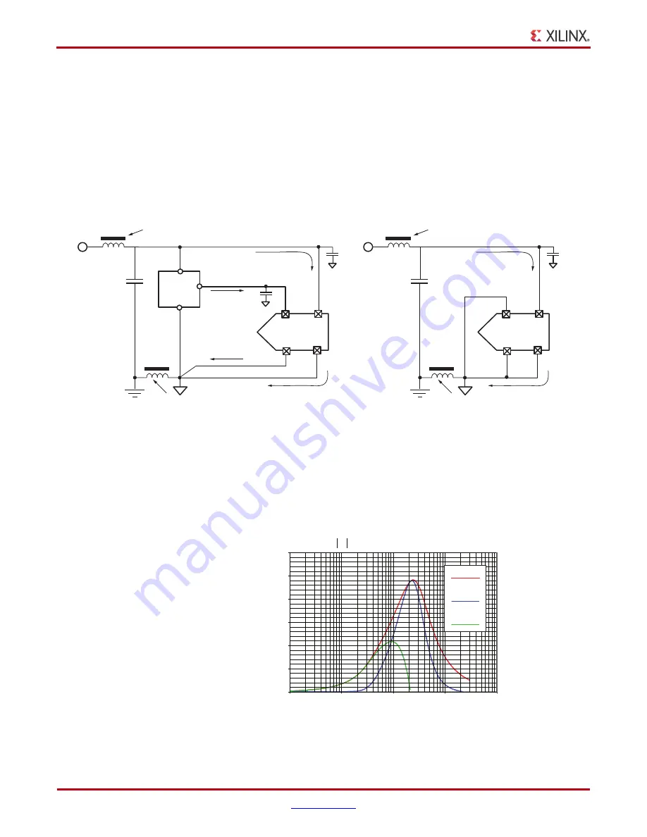
considered when designing the PCB. This is shown in
, where the
common ground impedance R
G
converts digital switching currents into a noise voltage for
the analog circuitry. However, it is often not possible or practical to implement a separate
analog ground plane in a design. One solution is to isolate V
REFN
and AV
SS
, ground
references (such as a trace) from the digital ground (plane) using a ferrite bead (
The ferrite bead behaves like a resistor at high frequencies and functions as a lossy
inductor. A typical ferrite impedance vs. frequency plot is shown in
. The ferrite
helps provide high frequency isolation between digital and analog grounds. The reference
IC maintains a 1.25V difference of between V
REFP
and V
REFN
. The ferrite offers little
resistance to the analog DC return current.
X-Ref Target - Figure 24
Figure 24:
System Monitor ADC Power and Ground Connections
ADC
2.5V ±5%
~ 12 mA
~ 12 mA
10 nF
470 nF
V
CCAUX
10 nF
AV
DD
AV
SS
V
REFP
V
REFN
Digital
Ground
Reference
Analog Ground Trace
Ferrite beads provide
high frequency isolation
External Reference
~ 50 µA
~ 50 µA
REF3012
REF3112
MAX6018
Filter V
CCAUX
supply
ADC
2.5V ±5%
~ 12 mA
~ 12 mA
470 nF
V
CCAUX
10 nF
AV
DD
AV
SS
V
REFP
V
REFN
Ferrite beads provide
high frequency isolation
On-Chip Reference
UG370_24_042910
Filter V
CCAUX
supply
X-Ref Target - Figure 25
Figure 25:
Ferrite Impedance Versus Frequency Plot
Impedance (
Ω
)
UG370_25_060809
Frequency (MHz)
Z , R, and X
L
vs Frequency
X
L
R
Z
Z
R
X
L
200
400
600
800
1000
1200
0
100
10
1
1000
10000
www.BDTIC.com/XILINX


