Virtex-6 FPGA System Monitor
19
UG370 (v1.1) June 14, 2010
Register File Interface
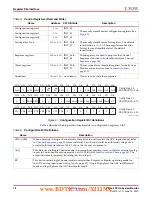
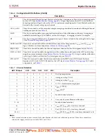
EC
This bit is used in Single Channel Mode to select either Continuous or Event driven sampling mode
for the ADC
(see
System Monitor Timing, page 33
). A logic High places the ADC in event driven
sampling mode and logic 0 places the ADC in continuous sampling mode. Event Mode should only
be used with external analog input channels.
AVG1, AVG0
These bits are used to set the amount of sample averaging on selected channels in both Single Channel
and Sequence mode (see
CAVG
This bit is used to enable averaging for the calculation of the calibration coefficients. Averaging is
enabled by default (logic 0). To disable, set this bit to logic 1. Averaging is fixed at 16 samples.
OT
This bit is used to disable the Over
-Temperature signal. Alarm is disabled by setting this bit to logic
1 (see
ALM0 to ALM2 These bits are used to disable individual alarm outputs for Temperature, V
CCINT
, and V
CCAUX
. A
logic 1 disables an alarm output (see
SEQ0, SEQ1
These bits are used to enable the channel-sequencer function for the bit assignments (see
CAL0 to CAL3
These bits are used to enable the application of the calibration coefficients to the ADC and on
-chip
supply sensor measurements (
see
System Monitor Calibration, page 31
). A logic 1 enables calibration
and a logic 0 disables calibration. For bit assignments, see
.
CD0 to CD7
These bits are used to select the division ratio between the
DRP clock (DCLK) and the lower
frequency ADC clock (ADCCLK) used for the ADC
(see
System Monitor Timing, page 33
). For bit
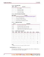
Table 7:
Channel Selection
ADC Channel
CH4
CH3
CH2
CH1
CH0
Description
0
0
0
0
0
0
On
-chip temperature
1
0
0
0
0
1
Average on
-chip V
CCINT
2
0
0
0
1
0
Average on
-chip V
CCAUX
3
0
0
0
1
1
V
P
, V
N
—Dedicated analog inputs
4
0
0
1
0
0
V
REFP
(1.25V)
(1)
5
0
0
1
0
1
V
REFN
(0V)
(1)
6
0
0
1
1
0
Invalid channel selection
7
0
0
1
1
1
8
0
1
0
0
0
Carry out a System Monitor calibration
9.....15
...
...
...
...
...
Invalid channel selection
16
1
0
0
0
0
V
AUXP
[0], V
AUXN
[0]—Auxiliary channel 1
17
1
0
0
0
1
V
AUXP
[1], V
AUXN
[1]—Auxiliary channel 2
18....31
...
...
...
...
...
V
AUXP
[2:15], V
AUXN
[2:15]—Auxiliary channels 3 to 16
Notes:
1. These channel selection options are used for System Monitor self-check and calibration operations. When these channels are
selected, the supply sensor is connected to V
REFP
and V
REFN
.
Table 6:
Configuration Bit Definitions
(Cont’d)
Name
Description
www.BDTIC.com/XILINX


