background image

8825/8830 DDS User Guide/57

Scanning to the Network (SCAN mode)

The 8825/8830 DDS has two scanning modes of operation: COPY mode
and SCAN mode.

Note:  the SCAN mode is optional on the 8825 DDS; it is a standard feature
on the 8830 DDS.  The SCAN MODE option may be enabled at any time on
the 8825 DDS.  For ordering information, contact your Xerox representative.


In COPY mode, documents are scanned, temporarily stored in memory
or the internal hard disk, and then sent to the local Printer as soon as the
printer is available.  When the next job is scanned, the file from the
previous job is automatically deleted from the hard disk, making room
for new files.  Operation of the system works as described in the
previous sections.


In SCAN mode, the image file created by scanning is stored directly onto
the hard disk for later retrieval over a connected network by a remote
system.  The image is stored in Tagged Image File Format (TIFF) 6.0,
using CCITT Group 4 compression.

Files stored in SCAN mode may be retrieved over the network.  After the
file is retrieved by the Document Retrieval Tool (DRT) program running
on a network-connected computer, the copy residing on the local hard
disk is deleted automatically. For more information, refer to the
Document Retrieval Tool User Guide.

Other remote retrieval programs, using the File Transfer Protocol (FTP),
may also retrieve and delete files from the 8825/8830 DDS hard disk
over the network.  These other programs will copy, rather than move, the
files, so the file remains on the local hard disk after retrieval.

After a file has been on the local hard disk for longer than the time specified
for the FILE DELETION Timer, the system automatically deletes the file.

To set the value for the FILE DELETION Timer, go to the 

Timers section of

this manual.

Switching between COPY mode and SCAN mode

To switch between the COPY mode and the SCAN mode, perform the
following steps:

1.  Ensure that the READY TO COPY screen is displayed.  If a menu is

displayed, press the Menu key to return to the READY... screen.  If
Please Enter Account is displayed, enter a valid account number to
obtain the READY... screen.

2. Press 

the 

Mode key.  The system switches to the SCAN mode, and the

screen now displays READY TO SCAN.  Pressing the Mode key again
returns to the COPY mode.

Note:  the TCP/IP network protocol must be enabled in the Controller, or the
8825/8830 DDS will not enter the SCAN mode.  To enable the TCP/IP
protocol, refer to the Controller Setup Manual.

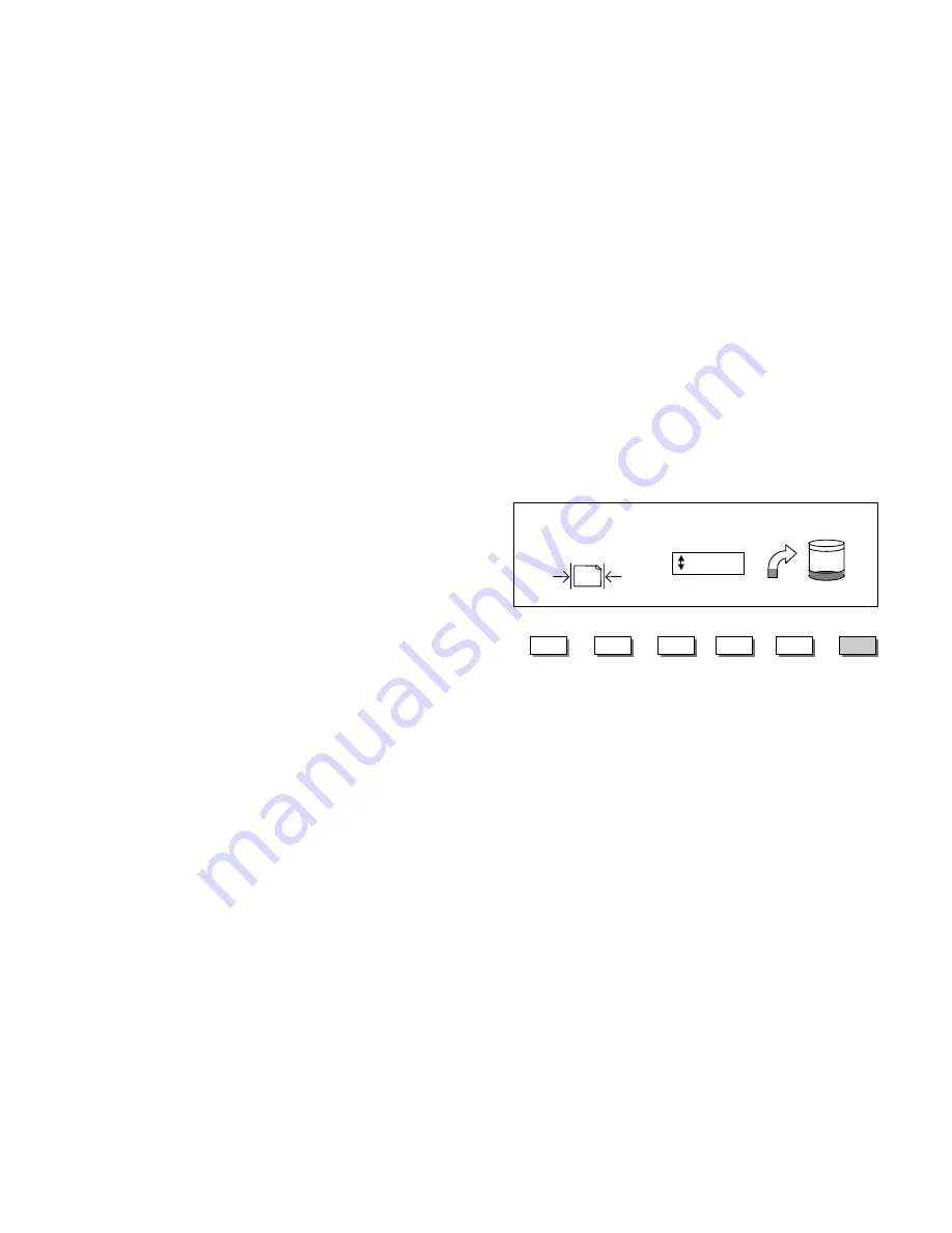
READY TO SCAN
INSERT DOCUMENT

Enter

Next

Exit

Mode

Menu

AUTO

Previous

   400 DPI

Summary of Contents for Synergix 8830

Page 1: ...8825 8830 Digital Document System User Guide 701P30070 June 1999...

Page 2: ...ising out of any inaccuracies or omissions Xerox Corporation Multinational Customer and Service Education 800 Philips Road Building 845 17S Webster NY 14580 USA All terms mentioned in this document th...

Page 3: ...erials for purposes other than what they were intended Keep all supplies and materials out of the reach of children Do not use the units near water wet locations or outdoors The components of this pro...

Page 4: ...prevent operator access to unsafe areas Covers guards and interlock switches are provided to ensure that the system will not operate with the covers opened Unplug the reprographic system from the wal...

Page 5: ...good quality document 23 What is a bad quality document 24 AutoIQ 26 Automatic adjustment of copy quality 26 Automatic edge detection and document centering 26 Scanning strategies 27 The Background Su...

Page 6: ...RRUPT Timer 71 FILE DELETION Timer 71 Adjusting a timer 71 Scanner Control 72 System Information menu 73 System Description 73 Recent Faults List 74 Configuration Print 74 User Accounting 74 System Ad...

Page 7: ...ing jobs 110 Using the 8825 8830 DDS with Job Accounting 110 Submitting Jobs from the Scanner 110 Submitting jobs over the network 111 Terminating use under an account 111 Cleaning and Maintenance Sca...

Page 8: ...8825 8830 DDS User Guide iv Notes...

Page 9: ...ured images in engineering or architectural sizes The output from the printer can be further processed by the addition of the Online Folder Printing copying and scanning to the network can be done con...

Page 10: ...o automatically make the image quality adjustments that yield a good copy even from poor original documents AutoIQ also automatically detects the width and adjusts the centering of a scanned original...

Page 11: ...4 6 00 15 24 4 00 10 16 4 00 10 16 Line scan mode 100 1 bit 6 00 15 24 6 00 15 24 4 00 10 16 4 00 10 16 Mixed copy mode 300 4 bit 1 0 2 54 4 00 10 16 0 89 2 03 2 67 6 78 Photo copy mode 200 8 bit 2 00...

Page 12: ...de serves two purposes it helps guide the document through the scanner and it serves as a target of known reflectivity during calibration of the scanner s cameras This calibration known as normalizati...

Page 13: ...es and contains a Graphical Display for the communication of information and instructions The display may be adjusted upward for better viewing Underneath the display are buttons for viewing selecting...

Page 14: ...EEP function is enabled factory default a beep sound will be heard when a key is pressed If an improper key is pressed a multiple beep sound will be heard Media Selection The Source button selects the...

Page 15: ...illuminates The CUSTOM OUTPUT FORMAT screen is displayed Press the Next key to select WIDTH or LENGTH Press the Enter key to confirm the choice Enter a value using the Numeric Keypad Note the entered...

Page 16: ...cator illuminates The SELECT OUTPUT FORMAT screen is displayed Press the Next key or the Previous key to select an item from the list Press the Enter key to confirm the choice Note formats may be adde...

Page 17: ...the selection The speeds are shown in Table 2 Table 2 Scanning Resolutions and Speeds 7356 7346 Mode DPI Pixel Depth Min IPS cm s Max IPS cm s Min IPS cm s Max Line copy mode or scan mode 400 1 bit 3...

Page 18: ...suppressed but the foreground image is improved to increase the contrast This selection works best for documents with medium levels of colored background on opaque media or for documents on transluce...

Page 19: ...nt Pressing the associated key allows the operator to select one of three reduction enlargement modes Auto automatically adjusts the reduction enlargement to fit the size of media selected Manual allo...

Page 20: ...eing displayed pressing this key exits the menus and directly returns to the previous Ready state The Previous key highlights the previous item in a displayed list The Next key highlights the followin...

Page 21: ...e COPY mode the scanned image or set of images is printed on the Printer In the SCAN mode the image or set of images is stored on the hard disk for later retrieval over a network by a client running o...

Page 22: ...buttons for controlling the scanning and printing of images To the left of some of the buttons are status indicator lamps that illuminate when the associated feature has been selected If the operator...

Page 23: ...and external communications are checked and the internal cameras are normalized using the Document Hold down Guide as a color reference Note if the guide is not installed when the Scanner is switched...

Page 24: ...fy that the power switches on the equipment are in the off 0 position 2 Connect the power cords to the equipment and to the electrical mains 3 Connect the Scanner and its DDS User Interface to the Con...

Page 25: ...Controller and the Printer There are two styles of power switching Style A has a separate switch for the Controller and the Printer For Style A systems first switch on the Controller Power Switch the...

Page 26: ...e opened by pressing the red button Style C has a power switch only for the Printer A circuit breaker interrupts power to both the Controller and the Printer To switch off the Controller the circuit b...

Page 27: ...nd the Printer The Controller and the Printer Please refer to the User Guide for the 8830 Printer for instructions for installing media and other consumable supplies as well as detailed operating inst...

Page 28: ...l indicate READY TO COPY Your digital copier system is now ready to make copies Loading Media and other consumable supplies Please refer to the User Guide for the 8830 Printer for instructions about l...

Page 29: ...engages the feed rolls The Scanner transports the document to the starting position then scans the document The resulting image is electronically sent to the printer and your copy is printed The docum...

Page 30: ...tain both line elements and photo elements or halftone images Photo documents are continuous tone or grayscale images Note for Photo documents no background suppression is allowed Background Suppressi...

Page 31: ...ument Good quality documents are easy to scan They usually require no adjustments to the default values to create good line drawing images A good quality document has all of these characteristics High...

Page 32: ...rtunately the 8825 8830 DDS incorporates special image processing technology that can extract acceptable images from documents degraded by many kinds of problems A bad quality document has one or more...

Page 33: ...or more densities or colors Examples include pencil additions on an ink drawing or pencil or ink additions to a sepia Dark or medium dark background Example underexposed blueprint Background has varia...

Page 34: ...oreground image Note always load the side with both background and text or lines first AutoIQ will use both the white and black information and automatically find the best settings This will produce a...

Page 35: ...py Evaluate the printed image Adjust the Copy contrast settings if necessary and make another copy Mix of Lines text and halftones error diffused images or continuous tone documents Select Mixed as th...

Page 36: ...Image Quality Copy keys Light Use this setting for documents with colored or translucent background with higher contrast between foreground and background than Dark documents but less contrast than n...

Page 37: ...can according to these guidelines First group the documents by media type e g blueprint pencil sepia and so forth By scanning groups of documents that are the same type you will minimize the number of...

Page 38: ...elected copy size The size of the output media must be known in advance for this feature to operate so Auto is not a valid selection if both the Synchro cut feature and the Auto media source feature a...

Page 39: ...SI and ARCH sizes are enabled 71 and 141 if the ISO A or ISO B sizes are enabled up to six additional preset values if these values are defined using the CUSTOM R E PRESETS menu function This function...

Page 40: ...feature is Menu CONFIGURATION SCANNER CONTROL AUTO SCAN Options ENABLED or DISABLED To enable or disable AUTO SCAN perform the following steps 1 Ensure that the READY screen is displayed 2 Press the M...

Page 41: ...steps 1 Ensure that the READY screen is displayed 2 Press the Menu key 3 Press the Next key until CONFIGURATION is selected 4 Press the Enter key 5 Press the Next key until SCANNER CONTROL is selecte...

Page 42: ...rotation of the image is required if possible in order to obtain the fastest processing time For example if an A size copy is required on a 12 inch 30 48 cm roll feed the original with the short edge...

Page 43: ...rmat to Preset and select the desired page size This setting cuts the media to a previously defined length that the operator chooses 4 Press the Next or Previous keys until the desired output size is...

Page 44: ...on and Enlargement feature and the Online Folder you must orient and insert the document title block in the same orientation as the resulting enlargement or reduction copy size In addition the recomme...

Page 45: ...ter Media Roll Width Input Title Block Position Recommended Printer Media Roll Width Input Title Block Position Recommende d Printer Media Roll Width ANSI ARCH ANSI ARCH ANSI ARCH ANSI ARCH ANSI ARCH...

Page 46: ...ess a copy job immediately press the Printer Interrupt key The associated status lamp illuminates and the current pages of the most current remote print job are completed Usually a maximum of two page...

Page 47: ...at image using all of the recalled settings When the Store Recall key is pressed the STORE RECALL screen is displayed Recalling the last job Press the Enter key to select LAST JOB The LAST JOB screen...

Page 48: ...job images and parameters are deleted Press the Enter key to return to the READY screen Storing Job Templates Groups of settings associated with a job may be stored in memory as templates Up to 9 such...

Page 49: ...e choice The settings from the current copy job are saved at the location entered and a confirming message is displayed The operator may choose to replace the contents of a used location with the curr...

Page 50: ...RECALL TEMPLATE screen is displayed The storage locations that actually contain templates are shown Use the numeric keypad to enter the number of the template to be recalled Press the Enter key to co...

Page 51: ...d as the default selections Press the Start Recall key Press the Next key until SAVE DEFAULT TEMPLATE is highlighted Then press the Enter key to confirm the choice Ensure that all the options under Me...

Page 52: ...key until DELETE TEMPLATE is highlighted Press the Enter key to confirm the choice The DELETE screen is displayed Enter the template number to be deleted Press the Enter key to confirm the choice The...

Page 53: ...tly stored and may be recalled as the active defaults Press the Store Recall key Press the Next key until RECALL FACTORY DEFAULTS is highlighted Then press the Enter key to confirm the choice Press th...

Page 54: ...mation associated with that particular device If the finisher is a Folder the screen lists the available types of folding that the connected Folder offers The screen shown opposite is an example Note...

Page 55: ...red to the rear of the Scanner after the scan If the CONFIGURATION SCANNER CONTROL DOCUMENT RETURN parameter is set to REAR then all documents are delivered to the rear after scanning The 7346 7356 Sc...

Page 56: ...ss the Next or the Previous key to select FORWARD or REVERSE collation Press the Enter key to confirm the choice The READY TO BUILD SET screen is displayed Insert each document of the set one at a tim...

Page 57: ...is point the operator may make further changes to the Media Source selection and the Reduction Enlargement value Any such change will be applied to that printing of the entire set After the printing o...

Page 58: ...o mode has been selected the lead margin is added before the image is printed and the trail margin is added after the media cut signal is received from the scanner Thus the length of the media from th...

Page 59: ...s displayed For the X direction the choices are LEFT CENTER and RIGHT For the Y direction the choices are TOP CENTER and BOTTOM Press the Next key or the Previous key to select X or Y and then the Ent...

Page 60: ...ice If the unit of measure has been set to MILLIMETERS refer to the References section for instructions then MM appears next to each value If INCHES has been set then IN appears Press the Next key or...

Page 61: ...lt of the settings The values may be set in increments of 0 1 in or 1 0 mm and over a range of 4 to 4 in 100 to 100 mm Values outside the allowed range are rejected An edge of the image may be clipped...

Page 62: ...e Next key or the Previous key to select MIRROR Press the Enter key to confirm the choice The mirroring function can perform the following transformations Axis Transformation X Y XY OFF Press the Next...

Page 63: ...onverted into its photographic negative Press the Transform key Press the Next key or the Previous key to select INVERT Press the Enter key to confirm the choice Press the Next key or the Previous key...

Page 64: ...lead and trail edge of the image Press the Sample key The associated indicator lamp illuminates and the 8830 DSS is placed in PRINTER INTERRUPT mode The printer immediately prints a sample of the next...

Page 65: ...disk is deleted automatically For more information refer to the Document Retrieval Tool User Guide Other remote retrieval programs using the File Transfer Protocol FTP may also retrieve and delete fil...

Page 66: ...s the selected scanning resolution Press the Next or Previous key to select a value of 100 200 300 or 400 DPI A new value may be selected before each scan This icon shows how much Random Access Memory...

Page 67: ...h Specification of Finishing Options Since there is no physical output the finishing operations are not applicable Selection of Reduction Enlargement The electronic file is saved without alteration so...

Page 68: ...ctive account is deleted Press the C CA key again followed by the Enter key to delete the next to last scanned image This process can be repeated until all desired images are removed from the hard dis...

Page 69: ...under each account COUNT and the percentage of total disk space consumed by the account SIZE are shown Deleting Images The key operator may delete all of the images scanned under any account or all th...

Page 70: ...o confirm the choice 3 Enter the System Administrator password and press Enter The default password is 0 4 Press the Next key to select FILE SYSTEM Press Enter to confirm the choice 5 Press the Next k...

Page 71: ...icate that the list contains more items than are visible The selected list item is highlighted To view other items in the list and to change the selected item press the Next key or the Previous key To...

Page 72: ...AN OPTIONS LOCALIZATION MEDIA SERIES CUSTOM MEDIA FORMATS IMAGING CUSTOM R E PRESETS COPY OPTIONS SCANNER CONTROL CONTROL PANEL TIMERS CHANGE PASSWORD FILE SYSTEM JOB ACCOUNTING MAIN MENU DIAGNOSTICS...

Page 73: ...d imaging parameters Timers Sets the values for three timer functions a FEATURE the time that a non default feature remains in effect after the last actuation of a key b PRINTER INTERRUPT the time tha...

Page 74: ...uces a beep when a key is pressed Beeper The BEEPER setting allows the operator to enable or disable the beep sound that occurs when a key is pressed The two choices are ENABLED DISABLED The factory d...

Page 75: ...9 4 x 431 8 mm C 17 x 22 inches 431 8 x 558 8 mm D 22 x 34 inches 558 8 x 863 6 mm E 34 x 44 inches 836 6 x 1117 6 mm ARCH A 9 x 12 inches 228 6 x 304 8 mm B 12 x 18 inches 304 8 x 457 2 mm C 18 x 24...

Page 76: ...d in the CONFIGURATION LOCALIZATION DISPLAY UNITS screen To enter a format press the Next or the Previous key until the desired field is highlighted Enter the value for the field using the numeric key...

Page 77: ...To store or change custom R E values 1 From the COPY OPTIONS screen choose CUSTOM R E PRESETS The CUSTOM R E PRESETS screen is displayed 2 Press the Next key until the value you wish to change is high...

Page 78: ...Press the Enter key to place a check mark in the box and enable the autorotation option Press the Enter key again to remove the check mark and disable the option Press the Exit key to leave the IMAGIN...

Page 79: ...e FILE DELETION timer determines the amount of time that an image remains on the internal hard disk after being scanned in The timer only applies to files scanned when the 8825 8830 DDS is in the READ...

Page 80: ...matic detection of the width of the document and the automatic centering of the image ENABLED is the factory default If the feature is disabled the operator is prompted to manually enter the width of...

Page 81: ...the amount of Random Access Memory RAM and the size of the Hard Disk Drive are displayed Note the Folder is supplied in one of three configurations folding for ANSI ARCH architectural and ISO sizes I...

Page 82: ...ints User Accounting The USER ACCOUNTING screen allows access to a display of job accounting information for a specific user Please refer to the Job Accounting section for details Note on the 8825 DDS...

Page 83: ...rd Password entry When the SYSTEM ADMINISTRATION item is selected the user is immediately prompted for a password Enter the password on the numeric keypad and press the Enter key to confirm the entry...

Page 84: ...Printer These two passwords always have the same value Job accounting Selecting JOB ACCOUNTING provides direct access to the JOB ACCOUNTING menu From there the accounting system may be configured and...

Page 85: ...ntil the desired choice ENABLED or DISABLED is shown Then press the Enter key to confirm the choice Press the Exit key to leave the SECURITY SETTINGS screen Change Password Once a valid password has b...

Page 86: ...ocuments scanned This function is reserved for the Customer Service Engineer so the diagnostic password must first be entered Return to the PASSWORD screen and enter the diagnostics password if it has...

Page 87: ...TEST PRINT screen is displayed Press the Next key or the Previous key to select YES or NO Select YES to send the test print to the Printer Press the Enter key to confirm the choice PASSWORD Select thi...

Page 88: ...o use Press the Next key or the Previous key to scroll through the choices on any screen Press the Enter key to select the highlighted choice Press the Exit key to leave the screen Each test is explai...

Page 89: ...nner image The view of the left and right cameras must be adjusted to align with the view of the center camera The adjustment must be correct both for left to right alignment and front to back alignme...

Page 90: ...Left to right The illustration below shows two examples of incorrect left to right stitch adjustment Correct Not Correct Correct Camera 1 image Camera 2 image Camera 1 image Camera 2 image Stitch are...

Page 91: ...CAUTION Once the reading of the disk has begun the upgrade process must be allowed to complete Do not allow any interruption of power to either the Scanner or the Controller during the upgrade proces...

Page 92: ...ent from the Scanner 2 Ensure that the Platen Glass and the surface of the Document Hold down Guide are completely clean If not clean both surfaces with Xerox Lens and Mirror Cleaner 43P81 Be sure to...

Page 93: ...f the test letter If the subtest is successful a P is displayed If a subtest fails an F will be displayed If an F is displayed call for service Note the test sequence will be executed until the operat...

Page 94: ...umber of times that test has been executed and passed If a test fails one or more times XX will be displayed in place of the number of successful test executions for that test If XX is displayed call...

Page 95: ...TION This test uses a black A A4 size piece of paper as a test pattern The alignment corrects for timing errors in the actuation of the Edge Present Sensor and the Edge Registered Sensor Perform this...

Page 96: ...correct the motor speed perform the following steps 1 Select MOTOR SPEED from the COMPONENT TESTS menu The MOTOR SPEED screen is displayed 2 Insert Test Pattern 082E11490 face down and with the short...

Page 97: ...edge is not positioned within the specification perform the REGISTRATION alignment 1 Obtain a black A A0 piece of paper The black paper test pattern supplied with the scanner may be used 2 Select REGI...

Page 98: ...COMPONENT TESTS menu The INPUT screen is displayed 4 Press the Start key 5 Using a folded piece of paper actuate each sensor and observe that the associated display goes from HIGH to LOW Deactuate eac...

Page 99: ...firm the choice For example highlight LAMP press the Enter key to enter the LAMP function then press Enter to switch the Lamp off and on Press the Exit key to leave the LAMP function To check the dire...

Page 100: ...er may ask you to provide this information when calling for service From the SCANNER DIAGNOSTICS menu press the Next key until READ NVR is selected Press the Enter key to confirm the choice The READ N...

Page 101: ...sed PMT or the DDS User Interface on the Scanner For example an account created on the DDS User Interface can be reset or deleted from the Printer Control Panel When the Scanner Job Accounting mode is...

Page 102: ...ccount and subaccount numbers are non significant and need not be entered so 3 03 or 0003 are all viewed as the same account For additional security parent account and subaccount numbers should be ass...

Page 103: ...and also under the account number of the submitting operator Users are charged for the area of media used rather than the linear length used On the display the usage is reported in square feet if INC...

Page 104: ...rriving through one of the communications ports on the Controller Such jobs are known as remote print jobs Job accounting for remote print jobs is controlled separately through the Printer Control Pan...

Page 105: ...for jobs that arrive from the Scanner 1 Press the Menu key on the DDS User Interface 2 Press the Next key until SYSTEM ADMINISTRATION is selected Press the Enter key to confirm the choice 3 Enter the...

Page 106: ...DISPLAY JOB ACCOUNTING JOB ACCOUNTING SETTINGS CHANGE PASSWORD PASSWORD JOB ACCOUNTING JOB ACCOUNTING JOB ACCOUNTING ACCOUNTING MODE ACCOUNT ADMINISTRATION RESET ALL ACCOUNTS CREATE FROM DISK CREATE A...

Page 107: ...created manually using the DDS User Interface or by means of a formatted file loaded from a disk Creating accounts manually From the ACCOUNT ADMINISTRATION screen choose CREATE ACCOUNTS The CREATE ACC...

Page 108: ...spreadsheet program may also be used Save the spreadsheet file as a tab delimited text file Loading the file Copy the file to an MS DOS formatted floppy disk Insert the disk into the floppy disk driv...

Page 109: ...an 20 subaccounts Delete some account subaccounts Then try again Note subaccounts were created until the limit was exceeded those created subaccounts remain valid Resetting existing accounts The Reset...

Page 110: ...S RESET will be displayed Press the Exit key to leave the RESET ALL ACCOUNTS screen Deleting accounts The system administrator can delete all job accounts an individual subaccount or a parent account...

Page 111: ...the message ACCOUNTS DELETED will be displayed Obtaining reports Useful reports about individual usage or system usage may be obtained from the job accounting system These reports may be displayed on...

Page 112: ...nu key to return directly to the READY screen Obtaining reports password required When performing the administration of the job accounting system it is possible to obtain reports two ways Display the...

Page 113: ...REPORT screen is displayed Enter the account number or the account subaccount number and press the Enter key The usage values will be displayed To view the usage values for an additional account enter...

Page 114: ...enabled 0 2 reserved 0 3 Tracks media used by jobs with no account number when Job Accounting is set to Optional and all media usage when Job Accounting is set to Disabled Also tracks media used for...

Page 115: ...rform the following steps 1 Ensure that a 3 5 inch floppy disk with MS DOS formatting is available 2 Insert the floppy disk into the disk drive of the Controller 3 From the REPORTS screen select WRITE...

Page 116: ...le explained later Restoring the account data from a floppy disk Accounting data previously saved to disk may be restored to the internal hard disk To perform these actions use the RESTORE FROM DISK f...

Page 117: ...the file may be in square decimetres or square feet When this file is written to the floppy with the WRITE TO DISK function the units will always be expressed as square decimetres All other records i...

Page 118: ...er key or press the Enter key directly In either case the READY screen is displayed and the user may scan and print copies If a valid account number has been entered all usage is charged to that accou...

Page 119: ...unt number is present the job is charged to system account 0 1 and also to system account 0 3 jobs with no account number just the same as if job accounting were disabled Enabling or disabling Job Acc...

Page 120: ...Glass If any smudges fingerprints or dirt are found particularly on the surface of the clear aperture then clean the glass with Lens and Mirror Cleaner 43P81 and a soft cloth Ensure that no dust or f...

Page 121: ...the Scanner is switched on 2 Ensure that the SCSI Address Switch on the Scanner is not set to 0 or 7 If so reset the switch to an address between 1 and 6 that is not used by any other connected SCSI d...

Page 122: ...nnected to the HOST SCSI connector on the Controller If so switch off all three units of the 8825 8830 DDS and connect the SCSI cable as shown Then switch on the Scanner the Controller and the 8830 Pr...

Page 123: ...t is outside allowable limits Normalization then fails and copy quality may not be satisfactory If this occurs Check that the Document Hold down Guide is installed before the Scanner is switched on Th...

Page 124: ...rolls b Roll up the document in the reverse direction to remove the curl then unroll the document and feed it again Images have gray areas caused by folds in the document Some relatively stiff docume...

Page 125: ...ents Switch on the Scanner Then switch on the Controller and the Printer 3 Connect the data cable CONTROLLER FAULT 50000001 CONTROLLER FAULT 50000002 The Controller has developed an internal fault mem...

Page 126: ...NTROLLER FAULT 50000012 MEMORY FULL CONTROLLER FAULT 5000013 MEMORY FULL The file system or memory is full 1 Retrieve or delete some documents to create more space Then rescan the document CONTROLLER...

Page 127: ...DISABLED d Open the top cover e Remove the plastic Document Hold Down Guide f Ensure that the Scanner is switched on g Manually actuate the front sensor The sensor should actuate easily with no stick...

Page 128: ...ny identifying product names and numbers are trademarks of XEROX Corporation All terms mentioned in this document which are known to be trademarks or service marks are appropriately capitalized Copyri...

Reviews: