


A
SSEMBLY
I
NSTRUCTION
A
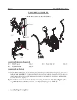
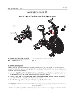
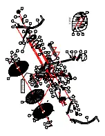
SSEMBLY STAGE
#5
Attach Pedals & Foot Rest to the Main Base Assembly
Assembly Hardware Required:
(*Assembly hardware may be preinstalled)
#26
Qty. 2
Pan Head Screw*
Assembly Description:
Assembly Note:
The right and left pedals are appropriately marked (R) and (L). The threading orientation on the left pedal is
reversed from the threading orientation on the right pedal. To avoid stripping of the threads on the pedals or crank arms, make sure
to follow the proper assembly orientation.
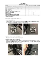
A)
Assemble the
Right Pedal
(#20) to the
Right Crank Arm
on the
Main Base Assembly
. Thread the pedal on the crank arm
(
clockwise
) and securely tighten with the pedal wrench (included). (Reference Figure #5)
B)
Assemble the
Left Pedal
(#21) to the
Left Crank Arm
on the
Main Base Assembly
. Thread the pedal onto the crank arm
(
counterclockwise
) and securely tighten with the pedal wrench (included).
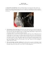
C)
Mount the
Bottle Cage
(#35) to the
Computer Mast
(#6) using 2-
Pan Head Screws
(#26).
Assembly Tip:
Take time to review the additional information regarding computer operation, product maintenance, and warranty.
Congratulations !
You have successfully completed the assembly of this product and you are ready to start exercising toward a healthier lifestyle!
P
AGE
8
Summary of Contents for AB-1
Page 14: ......


