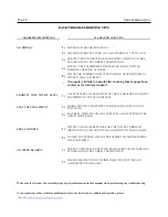
background image

P

AGE

 9 


T

ROUBLESHOOTING

BASIC TROUBLESHOOTING TIPS

BASIC TROUBLESHOOTING TIPS


PROBLEM DESCRIPTION 

SUGGESTED SOLUTION  


NO DISPLAY 

1)

CHECK BATTERY ORIENTATION: +  / - 


2)

CHECK BATTERY VOLTAGE: (2) AA BATTERIES 1.5 VOLTS EACH 


3)

CHECK CABLE CONNECTIONS: MAKE SURE CONNECTIONS ARE 

SECURE AND IN THE CORRECT ORIENTATION. 


4)

CHECK CABLE ASSEMBLIES FOR DAMAGE: PINCH POINTS &       

POSSIBLE SHORTING OF WIRES. 


5)

CHECK FOR POSSIBLE COMPUTER DAMAGE: CRACKED DISPLAY 

WINDOW (BLACK SCREEN). 


*

If computer still fails to operate after checking these suggestions, 

contact us for technical support. 


PRODUCT WILL NOT SIT LEVEL 

1)

USE LEVELERS ON THE BOTTOM OF THE STABILIZERS TO ADJUST 

EQUIPMENT TO UNEVEN SURFACES. 


SEAT POST MOVEMENT 

1)

MAKE SURE THE ADJUSTMENT KNOB IS LOCKED INTO A SEAT 

POST HOLE. 


2)

SECURELY TIGHTEN THE SEAT POST IN PLACE BY TURNING THE 

ADJUSTMENT KNOB. 


PEDAL WOBBLE 

1)

CHECK TO MAKE SURE PEDALS ARE INSTALLED CORRECTLY 

(ORIENTATION) AND MOUNTED FLUSH WITH THE CRANK ARMS. 


2)

LOOSEN THE PEDALS, CHECK FOR POSSIBLE CROSS-THREADING 

OF CRANK ARMS. 


NO SPEED READING 

1)

CHECK COMPUTER CONNECTION: MAKE SURE CONNECTORS ARE 

SECURE AND IN THE CORRECT ORIENTATION. 


2)

CHECK SPEED SENSOR. CONFIRM CABLE CONNECTION AND  

ALIGNMENT WITH MAGNET. 


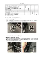
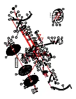
Make sure to reference the assembly steps & parts information in this manual when performing any troubleshooting.

I

f you experience other technical problems that are not listed or have additional questions, please 

check 

www.xebexfitness.com


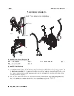
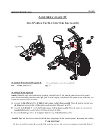
Summary of Contents for AB-1

Page 1: ...TYPRECAUTIONSBEFOREUSINGTHISPRODUCT REFERENCE ALL SAFETYGUIDELINESANDWARNINGLABELS RETAINPRODUCTLITERATURE FORFUTUREREFERENCE A S FETY OPERLYWARMUPAND STRETCHBEFOREEXERCISING IFYOUFEELPAINORDIZZINESSA...

Page 2: ...of stated precautions 2 Read all instructions and enclosed literature carefully Understand the assembly and operation before using the equipment 3 Use equipment on a flat level surface Use adjustment...

Page 3: ...RIGHT PEDAL SPRING WASHER 12 8 5 1 5T WASHER 18 8 5 1 5T BOLTS M5 10 LENGTH PAN HEAD SCREW CONNECTING ARM PREINSTALLED LEFT PIVOT ARM ASSEMBLY RIGHT PIVOT ARM ASSEMBLY FOOT REST LEFT PEDAL CONSOLE CO...

Page 4: ...Y SOMEITEMSMAYBEPREASSEMBLED THEEXPLODEDPARTSVIEWISSHOWNFORREFERENCEONLY SOMEITEMSMAYBEPREASSEMBLED PLEASEREFERTOTHEINDIVIDUALASSEMBLYSTAGEINSTRUCTIONSFORDETAILEDPARTSORIENTATION PLEASEREFERTOTHEINDIV...

Page 5: ...B Assemble theRearStabilizer Assembly 3 totheMainBase Assembly 1 using2 ButtonHeadAllenBolt C Use theAdjustableLevelerson thebottomof theStabilizerAssembliestoadjustthebikeand keep itfromrocking on a...

Page 6: ...correspondingmountingarea of theBaseFrameAssembly Securethemast tothe baseframe using 2 Button HeadAllenBolts 22 2 SpringWashers 23 and 2 Washers 24 B Install 2 C Batteriesinto the back oftheComputer...

Page 7: ...eat nolongertwistsortilts SeatAdjustments Adjust theseat heightby unscrewingandpullingout ontheSeatPostAdjustment Knob 12 Select a desired seat post height and retighten theknobuntil seatpost issecure...

Page 8: ...sof theBaseFrameAssembly 1 Using a standardcrescentwrench not included threadeach shaftinto the pivot boss using a clockwiserotation Fully tighten each shaft until itis flush against the pivot bossof...

Page 9: ...emble theRightPedal 20 to theRightCrankArmonthe MainBase Assembly Threadthepedal onthe crankarm clockwise and securely tightenwith the pedal wrench included Reference Figure 5 B AssembletheLeftPedal 2...

Page 10: ...E STABILIZERS TO ADJUST EQUIPMENT TO UNEVEN SURFACES SEAT POST MOVEMENT 1 MAKE SURE THE ADJUSTMENT KNOB IS LOCKED INTO A SEAT POST HOLE 2 SECURELY TIGHTEN THE SEAT POST IN PLACE BY TURNING THE ADJUSTM...

Page 11: ...ilizerwheelstouch thefloor Donotusethecomputerorpivotarmstomovetheunit Youmaywishtolockthefanin place whichwillkeepthearmsfrommoving byturningthesafetyknob referencedonpage7 untilitmakescontactwiththe...

Page 12: ...tighten handlebar assembly peg nut with 22mm socket wrench Note There will be a little play in these arms after tightening but this is normal XEBEX AIR BIKE Maintenance Information Service Daily Month...

Page 13: ...n movement To adjust the chain use the 15mm wrench to loosen the crank axle nut by rotating the wrench counter clockwise Once the axle nut is loosened use the 10mm wrench to turn the chain tensioner n...

Page 14: ......

Page 15: ...ER ARM 17 1PC FOOT REST 18 2PC LEFT PEDAL 20 1PC RIGHT PEDAL 21 1PC BUTTON HEAD ALLEN BOLT M8 20L 22 6PC SPRING WASHER 23 12PC WASHER 18 8 5 1 5T 24 14PC BOLT M5 10L 25 2PC PAN HEAD SCREW M5 10L 26 2P...

Reviews: