


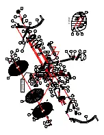


A
SSEMBLY
P
ARTS
L
ISTING
P
AGE
2
ITEM#
Q'TY
1
1
2
1
3
1
4
1
5
1
6
1
7
1
8
1
9
1
10
1
15
2
16
1
17
1
18
2
20
1
21
1
22
6
23
12
24
14
25
2
26
2
30
2
31
2
32
2
35
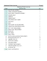
1
CAGE , WATER BOTTLE
PIVOT BOLT M8*35 LENGTH
SPACER WASHER 12*8.2*3.5T
NYLON NUT M8
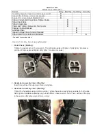
RIGHT PEDAL
SPRING WASHER 12*8.5*1.5T
WASHER 18*8.5*1.5T
BOLTS M5*10 LENGTH
PAN HEAD SCREW
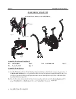
CONNECTING ARM (PREINSTALLED)
LEFT PIVOT ARM ASSEMBLY
RIGHT PIVOT ARM ASSEMBLY
FOOT REST
LEFT PEDAL
CONSOLE
CONSOLE MAST
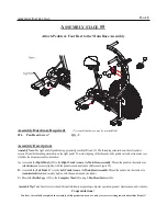
ADJUSTABLE SEAT SLIDER
SEAT POST
SEAT
SEAT SLIDER ADJUSTABLE KNOB
A
SSEMBLY
P
ARTS
L
ISTING
DESCRIPTION
BASE FRAME ASSEMBLY
FRONT STABILIZER ASSEMBLY
REAR FRONT STABILIZER ASSEMBLY
SENSOR CABLE
BUTTON HEAD ALLEN BOLT M8*20 LENGTH
Summary of Contents for AB-1
Page 14: ......


