


Model 590-10
Page 7
© 2002 Xantech Corporation
DOOR CHIME ACTIVATED SYSTEM
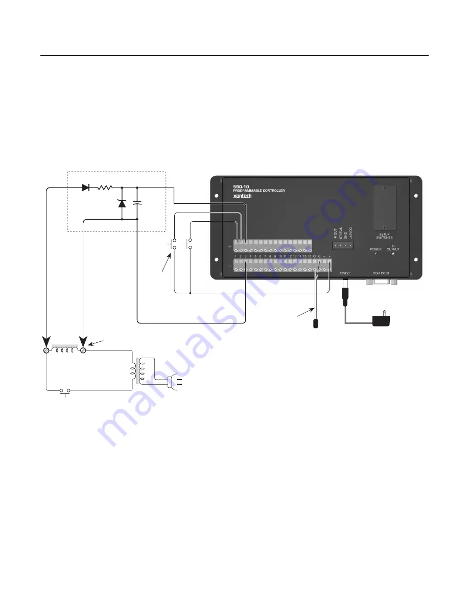
The circuit below,
Figure 9
, shows a simple means of using a door chime or door bell to activate one of the inputs
on a Xantech Model 590 Programmable Controller, to initiate a system function or functions. Functions that may
be initiated by this system, might include the following:
•
Switch the AV system source selector to a front door surveillance camera.
• Turn on front door intercom.
• Mute the audio in an A/V system.
The circuit uses a rectifier and a zener regulator to take the 24 to 28 volts AC from the chime coil and convert it to
the necessary 12 volts DC to drive the input on the controller.
1N914
Emitter
(attach to controlled device)
1 K ohm 1/4 W
12 Volt
Zener
1 µFd
50 V
120 V AC
120 VAC
Chime Coil
Chime
AC Transformer
Door Chime
Pushbutton
Switches
For
Other
System
Devices
Rectifier & Regulator Circuit
24 to 28
V AC
Connect circuit to chime
coil terminals as shown
+
786-00 Power
Supply
White
Striped Side
Figure 9 – Door Chime Activated System
To implement this circuit, proceed as follows:
1. Build the circuit using the parts shown.
2. Place the assembled parts in a small metal box.
3. Connect the input of the circuit to the chime coil terminals as shown.
Note: Do not connect it to the door chime push-button terminals!
4. Program the 590 with the necessary remote commands to drive the controlled components.
Caution
: Do not connect this circuit to any other terminals on the 590 except the pair of input terminals you wish
to assign to it!


