PH: 866.476.9217
5
COMPONENT LAYOUT DESCRIPTIONS
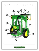
(See Figure 1, pg 4)
1.
AIR INLET
The air inlet is a 1" NPT opening with a full-port, Universal (Chicago type)
Coupling. The Coupling supplied is the recommended fitting for the
GO-A13-HA. Replacing the Coupling with a quick-connect type plug will
restrict air flow to the Impactor.
2.
THROTTLE VALVE
The Throttle Valve is a self-closing, lever-operated valve that is attached to
the right hand side of the frame on the Handle Assembly. The Throttle Valve
has a spring loaded lever, which shuts off air to the Impactor as soon as the
throttle is released. Only when the Throttle Lever is depressed will the
Impactor be activated.
3.
PIVOT PULL SWITCH
The Pivot Pull Switch is a pneumatic actuated valve that controls the
movement of the GO-A13-HA's wheels. When the Switch is in the PIVOT
position, the wheels will rotate so that they are parallel to the railcar. When
the Pull Switch is in the STRAIGHT position, the wheels will move
perpendicular to the railcar. The label located on the Pivot Guard, See
Figure 2, shows the Pull Switch position for the desired wheel movement.
4.
HEIGHT ADJUSTMENT LEVER
The Height Adjustment Lever is a pneumatic valve that controls the
movement of the GO-A13-HA's Impactor. When the Lever is pulled toward
the Operator the Impactor will rise to a max height of 24 inches off the
ground. By pushing the Lever away from the Operator of the Impactor will
lower to a minimum height of 10 inches off the ground. Once the Lever is
released the vertical lift cylinders mounted on either side of the chassis will
hold the Impactor in place to accommodate varying height capstans.
5.
FORWARD/REVERSE LEVER (F/R Lever)
Located in the rear of the Impactor (closest to the operator), the F/R Lever
controls the direction the Impactor will turn.


