


PRE-INSTALLATION
Greenstar FS CDi
ErP
6720818079 (2016/04)
12
FULLY PUMPED SEALED PRIMARY SYSTEM:
• A pressure relief valve [11] (spring loaded safety valve set to operate
at 3 bar) must be fitted to the heating return pipe as close as possible
to the boiler.
• An expansion vessel [9] must be fitted to the heating return pipe
close to the boiler and pressurised for the system volume according
to the instructions supplied with the vessel.
• A pressure gauge [10] (3 bar min.) must be fitted to the heating
return pipe.
• An automatic air vent must be fitted.
• Stop valve [12] must be a fixed cylinder type or sealed systems
approved connection.
SEALED SYSTEM LAYOUT
Fig. 6
Sealed system example configuration
3.4
Condensate pipe work
3.4.1
Internal connections
In order to minimise risk of freezing during prolonged cold spells, the
following methods of installing condensate drainage pipe should be
adopted, in order of priority.
Wherever possible, the condensate drainage pipe should be routed and
terminated so that the condensate drains away from the boiler under
gravity. A suitable internal foul water discharge point such as an internal
soil and vent stack. A suitable permanent connection to the foul waste
pipe should be used.
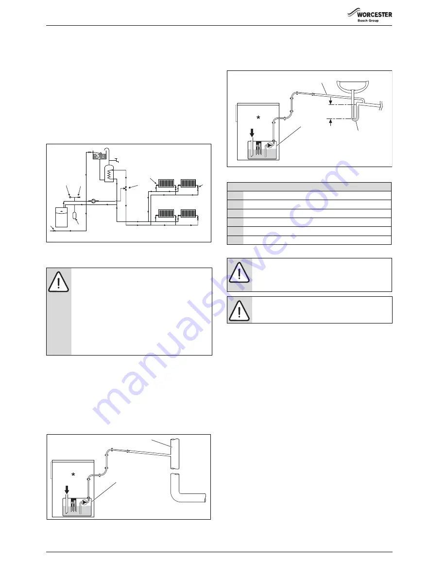
Fig. 7
Disposal to soil vent stack
Alternatively if the first option is not possible an internal kitchen or
bathroom waste pipe, washing machine waste pipe etc. can be used.
Ensure that the condensate drain pipe is connected “down stream” of
the waste trap.
Fig. 8
Disposal to a waste pipe
3.4.2
External connections
If no other discharge method is possible then the use of an externally run
condensate drainage pipe terminating at a suitable foul water discharge
point, or purpose-designed soak away, may be considered. If this
method is chosen then the following measures should be adopted:
▶ The external run be kept as short as possible and not exceed three
metres.
▶ The pipe should be run internally as far as possible before going
externally and the pipe diameter should be increased to 32mm
before it passes through the wall to the exterior. The pipe should be
insulated using suitable waterproof and weather resistant insulation.
▶ The external pipe should take the shortest and least exposed route to
the discharge point, and should "fall" as steeply as possible away
from the boiler, with no horizontal runs in which condensate might
stand.
▶ The use of fittings, elbows etc. should be kept to a minimum and any
internal “burrs” on cut pipe work should be removed so that the
internal pipe section is as smooth as possible.
NOTICE:
▶ Where a new or replacement boiler is being installed,
access to an internal “gravity discharge” point should
be one of the factors considered in determining
boiler location.
▶ The condensate pipe must be nominally
22mm Ø plastic pipe.
▶ The condensate pipe work must fall at least 52mm
per metre towards the outlet and should take the
shortest practicable route.
▶ Ensure there are no blockages in the pipe run.
6720648568-05.1W
o
11
9
10
12
Mains cold water
Cylinder
Heating flow
4
7
Hot water flow
8
Heating
return
14
1
return
3
6720648568-06.1Wo
2
1
Key to condensate illustrations
1
Condensate discharge from boiler
2
Condensate pump within boiler
3
Soil and vent stack
4
Sink or basin with integrated overflow
5
75mm sink waste trap
*
Condensate trap of 75mm already incorporated into the boiler
NOTICE:
Freezing conditions
▶ Pipe work length should be kept to a minimum and
the route as vertical as possible.
▶ Weather proof insulation must be used.
NOTICE:
Condensate waste
▶ Care should be taken when siting a soak-away to
avoid obstructing existing services.
75mm
min.
4
5
1
22mm Ø
6720648568-07.1W
o
2


