Manual 26489V1
Vertex-Pro Motor-Driven Compressor Control
Woodward
61
13.3
3.75
3.75
2.22
3.54
F9
F8
F7
F6
F5
F4
F3
F2
F1
38
1
37
74
F10
F11
F12
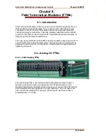
Figure 8-1—24/8 Analog FTM Outline Dimensions
Replacing a Fuse on the Field Termination Module (FTM)
1. Verify that the condition that caused the fuse to blow has been corrected.
If power has not been removed from the control system, power will
be active at the module and also at the FTM. Shorting of protected
circuitry could cause a control system shutdown.
2. Remove the FTM cover carefully, to prevent contact with any FTM circuitry
under the cover. To remove the FTM cover, pinch the retaining barb and lift
the cover.
3. Locate and replace the fuse with another fuse of the same size, type, and
rating,. See Figure 13-4 for channel fuse location.
4. Replace the FTM cover.
Summary of Contents for Vertex-Pro
Page 10: ...Vertex Pro Motor Driven Compressor Control Manual 26489V1 viii Woodward ...
Page 103: ...Manual 26489V1 Vertex Pro Motor Driven Compressor Control Woodward 93 Appendix C Declarations ...
Page 104: ...Vertex Pro Motor Driven Compressor Control Manual 26489V1 94 Woodward ...
Page 105: ...Manual 26489V1 Vertex Pro Motor Driven Compressor Control Woodward 95 ...
Page 106: ...Vertex Pro Motor Driven Compressor Control Manual 26489V1 96 Woodward ...
Page 107: ...Manual 26489V1 Vertex Pro Motor Driven Compressor Control Woodward 97 ...
Page 111: ......


