


Vertex-Pro Motor-Driven Compressor Control
Manual 26489V1
56
Woodward
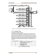
Fault Detection (I/O)
In addition to detecting module hardware faults, the application program may
detect I/O faults.
Analog Input Faults. The application software may set a high and low latch set
point to detect input faults.
Speed Sensor Input Faults. The application software may set a high and low
latch set point to detect input faults. The low latch set point must be greater than
one fiftieth of the frequency range.
Analog Output Driver Faults. The module monitors the source currents and
annunciates faults. The application determines the course of action in the event
of a fault.
Actuator Driver Or Load Faults. The module monitors the source and return
currents and annunciates faults. The application determines the course of action
in the event of a fault.
Micro-controller Faults. The system monitors a software watchdog, a hardware
watchdog, and a software watchdog on the VME bus communications. All
outputs are shutdown in the event of a microcontroller fault.
Troubleshooting Guide
If during normal control operation all of a chassis’ Analog Combo modules have
Fault LEDs on, check the chassis’ CPU module for a failure. If during normal
control operation only the Analog Combo module’s Fault LED is on or flashing,
insure that it is installed in the correct slot. If it is, then replace that Analog
Combo module. See instructions for replacement in Chapter 9, Installation. When
a module fault is detected, its outputs should be disabled or de-energized.
Speed Sensor Inputs
MPUs. If a magnetic pickup input is not functioning properly, verify the following:
1. Check that the cable is shielded and the shield is properly grounded per
the Shields and Grounding section in Chapter 9, Installation.
2. Measure the input voltage on the terminal block. It should be in the range
of 1–25 VRMS.
3. Verify that the signal waveform is clean and void of double zero
crossings.
4. Verify that no ground connection exists and that the resulting 60 Hz
signal is absent.
5. Measure the frequency. It should be in the range of 100 Hz - 25 kHz.
6. Verify that any unused MPU/Prox inputs are jumpered per Figure 9-16.
7. Check the wiring. Look for a loose connection at the terminal blocks and
disconnected or misconnected cables.
8. Check the software configuration to ensure that the input is configured
properly.
9. After verifying all of the above, exchange the J1 and J2 cables. If the
problem moves to a different channel, replace the cable. If not, replace
the Analog Combo module.
10. If the readings are incorrect on several channels of the module,
corresponding to both cables, replace the Analog Combo module.
11. If replacing the module does not fix the problem, replace the FTM. See
instructions for replacing the FTM in Chapter 9, Installation. The FTM
does not contain any active components on the MPU inputs, so replacing
it should be the last option.
Summary of Contents for Vertex-Pro
Page 10: ...Vertex Pro Motor Driven Compressor Control Manual 26489V1 viii Woodward ...
Page 103: ...Manual 26489V1 Vertex Pro Motor Driven Compressor Control Woodward 93 Appendix C Declarations ...
Page 104: ...Vertex Pro Motor Driven Compressor Control Manual 26489V1 94 Woodward ...
Page 105: ...Manual 26489V1 Vertex Pro Motor Driven Compressor Control Woodward 95 ...
Page 106: ...Vertex Pro Motor Driven Compressor Control Manual 26489V1 96 Woodward ...
Page 107: ...Manual 26489V1 Vertex Pro Motor Driven Compressor Control Woodward 97 ...
Page 111: ......