


Manual 26727
VariStroke-I (VS-I) Electro-hydraulic Actuator
Woodward
74
Chapter 6.
Configuration
Input Configuration
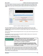
Figure 6-1. Input Configuration Screen
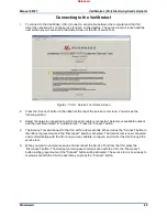
The analog input settings including scaling and diagnostics levels are displayed from this screen. The
values of the current operational and diagnostic settings are also displayed.
Analog Demand Inputs 1&2
Current Reading
: Displays the current value of the analog input signal in mA and percent of full stroke for
the analog input channels 1 and 2.
Analog Input Scaling
Minimum Analog Demand In:
Indicates the minimum input demand current
(4 mA default) that is used to position the actuator to 0%. Note only after VS-I shut down may values be
saved.
Maximum Analog Demand In:
Indicates the maximum input demand current (20 mA default) that is used
to position the actuator to 100%.
Fault Detection Thresholds, High/Low Limit:
Displays the fault detection limits of the analog demand
signals. Any demand signal below the Low Limit or above the High Limit will trigger an alarm.
Demand Input Configuration
Input Mode:
Allows selection of Single Channel 1, Single Channel 2, Dual Averaging, Dual Low Signal
Select, and Dual High Signal Select. If a Dual mode is selected, but only 1 signal is supplied, the actuator
will operate while outputting an alarm for the other signal.
Released