


Manual 26727
VariStroke-I (VS-I) Electro-hydraulic Actuator
Woodward
46
Input Power
The VS-I requires a power source capable of supplying the necessary output voltage and current at full
transient conditions. The maximum power in watts (W) of a DC source is calculated by multiplying the
rated output voltage by the maximum output current capability. The calculated power rating of the supply
should be greater than or equal to VS-I requirements. The electrical power supply should be able to
provide 2.3 A at 24 V (dc) continuously, with a peak of 10 A for 100 ms, 6 A for 4 seconds.
Cable selection and sizing are very important to avoid power loss during driver operation. The power
supply input at the driver’s input terminal must always provide the required nominal voltage for the driver.
The input power wire must comply with local code requirements and be of sufficient size such that the
power supply voltage minus the IR loss in the two lead wires to the VariStroke driver does not drop below
the driver input minimum voltage requirement.
The VS-I is not equipped with an input power disconnect. A means of disconnecting input power to the
VS-I must be provided for safe installation and servicing.
The VS-I is not equipped with input power protection. A means of protecting input power to the VS-I must
be provided. Breakers or fuses are intended to protect installation wiring and power sources from faults in
the VS-I or wiring. A circuit breaker meeting the requirements from the table below, or a separate
protection with the appropriate ratings, may be used for this purpose.
Table 3-2. Recommended Fuse Ratings or Circuit Breakers.
Components
Input Voltage
Steady
State
Input
Current
Maximum
Transient
Input
Current
Maximum
Power
Maximum Slow
Blow Fuse /
C.B. Rating
VS-I
(18 to 32) V (dc)
24 V (dc) nominal
3.1 A @
18 V (dc)
10 A
340 W
(100 ms)
20% above
Steady State
Current
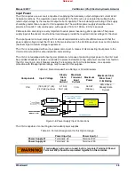
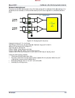
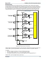
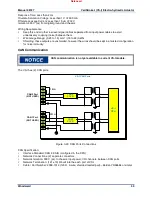
Figure 3-8. Power Supply Input Connections
The VS-I is capable of connecting two redundant power supplies.
Table 3-3. Terminal Assignment for this Option Usage.
Power Input (+)
Power Input (-)
Power Supply #1
Terminal # 38
Terminal # 37
Power Supply #2
Terminal # 36
Terminal # 35
If redundancy option is not used, both (+) signals (Terminal #36 and
Terminal #38) should be connected together on the terminal.
Released