


Manual 26727
VariStroke-I (VS-I) Electro-hydraulic Actuator
Woodward
26
Performance Index
The VariStroke product line is designed to bring a multitude of benefits to the actuation market place. One
the primary benefits a customer will realize is the VariStroke’s ability to combine high-speed actuation
with low-pressure hydraulic systems. To accomplish this, the VariStroke has utilized one of the largest,
commercially available servo valves in the world. This large servo valve allows the VariStroke to operate
at high speeds with only a single stage (i.e. no intermediate relay valves or second stage spool valves).
With this benefit, customers have quickly realized that they may have the ability make full strokes their
steam valve actuators much faster than they have in the past and, at the same time, still have very good
small signal & steady state response. While this combination of performance attributes (fast slew speeds
and good small signal response) is a primary feature of the VariStroke, there are limitations when paring
a large servo valve with a relatively small cylinder volume.
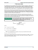
Before purchasing or installing a VS-I actuator, the user should verify that actuator will be operate
properly. As shown in the relationship below, the performance of the VS-I is dependent on Servo Valve
size, supply pressure, and the used cylinder volume. If the relationship below is satisfied, the actuator will
operate smoothly, with minimal overshoot and limit cycle.
If the relationship below is NOT satisfied, the actuator performance
will be compromised, resulting in excessive limit cycle and
accelerated wear. The actuator will also output a "Performance Index
Warning" alarm that cannot be disabled.
!"
#$%&'(%'
∗
+,
&-../0
1
2 ∗ 3
40/
5
6
∗ 7
&'8$9:
;
< =
Where:
>
? !!"#
$ %&''() >*+,,&*+ -. /01
2
3#"
$ 4)(-.5+* 2-67+8+* -. #:%'9::':8&
;
?<=>?@
$ %8*AB+ ;+.C8D -. #:%'9::':8&
Note:
This
is the
used
maximum stop position. It may or may not equal the Cylinder Length.
E%
F>G?<HG<
$ E6*-,8*AB+ 4A.,86.8
= 180
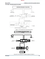
Figure 2-3 shows a graphical representation of the performance relationship for 4” (100mm), 5” (127 mm),
and 6” (150mm) Bore Actuators. There are no limits for stroke-pressure combinations for bigger i.e. 8”
(200mm) and 10” (250mm) Bore Actuators.
Released