


Manual 26727
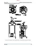
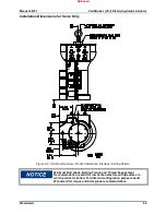
VariStroke-I (VS-I) Electro-hydraulic Actuator
Woodward
50
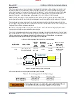
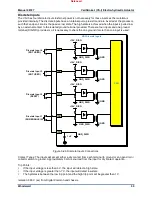
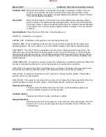
Cylinder Position Feedback Analog Inputs (Remote Servo Only)
There are two Final Cylinder Position Feedback analog inputs. Refer to the service tool chapter for
information on configuring these inputs.
Figure 3-13. Final Cylinder Position Feedback Analog Input Connections
Input Range: (0 to 25) mA, the recommended maximum range is (2 to 22) mA
Current Limit: 30 mA @ 25 °C
Calibrated Accuracy: 0.1% of full range @ 25 °C
Maximum Temperature Drift: 200 ppm/°C
Input Impedance: 235
Ω
±25
Ω
Loop power: +15 V ±0.5 V over temperature range
Max output current: 200 mA total (100 mA per sensor)
Common Mode Voltage Range: ±50 V(dc)
Common Mode Rejection Ratio: 70 dB @ 50 Hz & 60 Hz
Isolation: 500 V(ac) to chassis ground
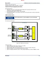
Overl15 V power output will result in unit reset and shut
down.
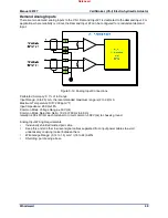
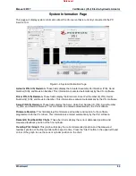
The following drawings illustrate correct and incorrect wiring methods to the Cylinder Position Feedback
Analog Inputs.
Figure 3-14. Cylinder Position Sensor Wiring Diagram When Using Vs-1 Internal Power
VS-I Cylinder Position Feedback
Analog Inputs
-
+
ADC
Converter
and
CPU
-
+
FEEDBACK
INPUT #1
FEEDBACK
INPUT #2
Current limiter
DGND
+15V
Feedback 1+
Feedback 1-
Current limiter
Feedback 2+
Feedback 2-
Released