Manual MRI3-ITER GB
Woodward
DOK-TD-MRI3 ITERE Rev.A
37
5.8 Indication of measuring and fault values
5.8.1 Indication
of measuring values
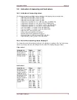
The following measuring quantities can be indicated on the display during normal service:
Apparent Current in phase 1 (LED L1 green)
Apparent Current in phase 2 (LED L2 green)
Apparent Current in phase 3 (LED L3 green)
Temperature
equivalent
A> in % (LED
A yellow), (for MRI3-ITE)
Temperature
equivalent
T
> in % (LED
T red), (for MRI3-ITE)
Temperature
equivalent
A
> in % (LED
> green), (for MRI3-ITER)
Temperature
equivalent
T
> in % (LED
> red), (for MRI3-ITER)
Time until release
T
in s (LED
T red), (for MRI3-ITE)
Time until release
T
in s (LED
> red), (for MRI3-ITER)
Apparent earth current (LED E green)
Active earth current (LED E and I
P
green) *
Reactive earth current (LED E and I
Q
green) *
Residual voltage U
E
(LED UE) only at ITER-relay type
Angle between I
E
and U
E
(only at ITER relay type)
5.8.2 Unit of the measuring values displayed
The measuring values can optionally be shown in the display as a multiple of the "sec" rated value
(xln) or as primary current (A). According to this the units of the display change as follows:
Phase current
Indication as
Range
Unit
Secondary current
Active portion I
P
Reactive portion I
Q
0.00 – 40.0
±.00 – 40
±.00 – 40.
x In
x In
x In
Primary current
.000 – 999.
k000 – k999
1k00 – 9k99
10k0 – 99k0
100k – 999k
1M00 – 2M00
A
kA*
kA
kA
kA
MA
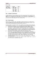
Earth current
Indication as
Range
Unit
Secondary current
Active portion I
P
Reactive portion I
Q
(E/SR/ER types)
.000 – 15.0
±.00 – 40
±.00 – 40.
x In
x In
x In
Secondary current
Active portion I
P
Reactive portion I
Q
(X/XR types)
0.00 - 150
±.00 – 150
±.00 – 150
% I
N
% I
N
% I
N
Primary earth
current
.000 – 999.
k000 – k999
1k00 – 9k99
10k0 – 99k0
100k – 999k
1M00 – 2M00
A
kA*
kA
kA
kA
MA


