background image

Woodward 

Manual MRI3-ITER GB 

64 

DOK-TD-MRI3 ITERE Rev.A 


Woodward Kempen GmbH 

Krefelder Weg 47 

 D – 47906 Kempen (Germany) 

Postfach 10 07 55 (P.O.Box) 

 D – 47884 Kempen (Germany) 

Phone: +49 (0) 21 52 145 1 


Internet 

www.woodward.com 


Sales 

Phone: +49 (0) 21 52 145 216 or 342 

 Telefax: +49 (0) 21 52 145 354 

e-mail: [email protected]


Service 

Phone: +49 (0) 21 52 145 614 

 Telefax: +49 (0) 21 52 145 455 

e-mail: [email protected]


Summary of Contents for MRI3-ITE

Page 1: ...MRI3 ITE R Time overcurrent relay with thermal replica and earth current measuring Manual MRI3 ITER Revision A...

Page 2: ...serves the right to update any portion of this publication at any time Information provided by Woodward Governor Company is believed to be correct and reliable However no responsibility is as sumed by...

Page 3: ...5 3 7 Parameter switch external triggering of the fault recorder 28 5 4 Protection parameters 29 5 4 1 Pickup value of the thermal overload protection IB A and IB T 29 5 4 2 Constant k 29 5 4 3 Energi...

Page 4: ...TE 41 6 4 3 Checking the input circuits and measured values 41 6 4 4 Example of a test circuit with earth fault directional feature 42 6 4 5 Checking the operating and resetting values of the relay 43...

Page 5: ...tected taking into account its initial load The MRI3 ITE R furthermore provides a universal time over current and earth fault protection with the following functions Integrated determination of earth...

Page 6: ...nt inverse time and definite time over current relay both for phase and earth faults determination of earth short circuit fault direction for systems with isolated or compensated neutral point Display...

Page 7: ...onnections Figure 3 1 Connection diagram Figure 3 2 Phase current measuring and earth current detection by means of Holmgreen circuit This connection can be used with three existing phase current tran...

Page 8: ...ctional detection Figure 3 4 Measuring of the phase voltages for the directional detection at earth fault protection IE and IE 3 1 1 Analogue input circuits The protection unit receives the analogue i...

Page 9: ...arm Apart from the relay for self supervision all protective functions can be op tionally assigned Relay 1 C1 D1 E1 and C2 D2 E2 Relay 2 C3 D3 E3 and C4 D4 E4 Relay 3 C5 D5 E5 Relay 4 C6 D6 E6 Relay 5...

Page 10: ...havior of the fault recorder can be influenced No writing over If 2 4 or 8 recordings are chosen the complete memory is divided into the relevant number of partial segments If this max number of fault...

Page 11: ...ch memory segment has a specified storage time which permits setting of a time prior to the trigger event Via the interface RS485 the data can be read and processed by means of a PC with HTL PL Soft4...

Page 12: ...Woodward Manual MRI3 ITER GB 12 DOK TD MRI3 ITERE Rev A 3 3 Front plate Figure 3 8 Front plate MRI3 ITE Figure 3 9 Front plate MRI3 ITER...

Page 13: ...t to the alphanumerical display light up green during mea suring and red at alarm LEDs underneath the pushbutton SELECT RESET light up green during setting and inquiry of the setting values printed le...

Page 14: ...le Read Only Memory With this program the CPU of the microcontroller calculates the three phase in order to detect a possible fault situation in the protected object For the calculation of the current...

Page 15: ...e temperature according to which the object to be protected reaches its tripping value after expiry of a long time Trip k2 100 Adjustment of the nominal current with IB e g 1 IN and selection of an ov...

Page 16: ...pickup value in the MRI3 ITE is deter mined by IB the following relation is effective n k IB k For this purpose the temperature T that really prevails in the electrical equipment needs to be known Th...

Page 17: ...ulate the thermal equivalent n The last value n 1 the stationary final value max for the actual current the adjusted time constant and the time since the last calculation dt must be known Analogous fo...

Page 18: ...d current and the actual current the cooling down or warming up constant will be applied for calculation In In 1 warming up In In 1 cooling down If the relay is supplied by the mains to be protected i...

Page 19: ...ansformers supplying the relay Earth faults beyond the current transformers i e on the consumer or line side will not be detected Figure 4 4 Generator stator earth fault protection 4 5 2 System earth...

Page 20: ...idual voltage UE required for determining earth fault direction can be measured in three different ways depending on the voltage transformer connections refer to Table 4 1 Total current can be measure...

Page 21: ...ltage UE the ER XR relay type determines whether the line to be protected is earth faulted On non earth faulted lines the capacitive component Ic a of the total current precedes the residual voltage b...

Page 22: ...which for instance are caused an electric arc fault do not impair the protective function 4 7 Demand imposed on the main current transformers The current transformers have to be rated in such a way th...

Page 23: ...Switch failure protection CBFP after tripping C B Recorded fault data Phase currents earth currents and tempera ture equivalent SELECT RESET one time for each phase L1 L2 L3 E A and T Enquiry failure...

Page 24: ...IE Save parameter SAV ENTER Save parameter SAV ENTER for about 3 s Display of software version First part e g D21 Second part e g 1 00 TRIP one time for each part Setting of the transformer connec tio...

Page 25: ...erload low set element reached T Tripping at k 2 100 red continuously Temperature limit of trip element reached IB A Setting green continuously Setting switch point kA Setting red continuously Define...

Page 26: ...ripping red continuously IE tripped IE Setting green continuously Setting switching point IE tIE Setting red continuously Setting time delay tIE IE tIE Pickup red flashing Pickup of IE IE tIE Tripping...

Page 27: ...nt is 1380 A The parameter is set to 1500 A and on the display 1380 A are shown If the parameter is set to sec the value shown on the display is 0 92 x In Note The pick up value is set to a multiple o...

Page 28: ...ut RESET input SET2 Blocking input RESET input B_S2 Parameter switch RESET input R_S2 Blocking input Parameter switch B_FR External triggering of the fault re corder RESET input R_FR Blocking input Ex...

Page 29: ...tion of the thermal overload k IB might be exceeded for a short time The warning relay responds and the LEDs indicate energizing This excitation signal remains activated even after completion of the...

Page 30: ...he flashing LED the relay will be set to the most sensitive time setting value of the selected characte ristics after five minutes warning of flashing LED tI The most sensitive time setting value mean...

Page 31: ...acteristics for earth fault element CHAR IE not ER device type By setting this parameter one of the following 7 messages appears on the display DEFT Definite Time independent over current time protect...

Page 32: ...blocked refer to Chapter 5 7 1 5 4 21 Circuit breaker failure protection tCBFP The CB failure protection is based on supervision of phase currents during tripping events Only af ter tripping this prot...

Page 33: ...ge is initiated after recognition of a general activation TRIP Storage is initiated after a trip has occurred A_PI After Pickup Storage is initiated after the last activation threshold was fallen shor...

Page 34: ...ed or TR_B the tripping stages are blocked The settings can be changed by actuating the keys or In this procedure the LEDs I I IE IE are simultaneously alight in case of protective blocking PR_B and L...

Page 35: ...or several of the four output relays can be assigned to element I as alarm relays At the same time the selected alarm relays for element I are indicated on the display Indication 1_ _ _ means that ou...

Page 36: ..._ I green tI Trip X 1 _ _ _ tI green I Alarm X _ _ 3 _ I green tI Trip X 1 _ _ _ tI green IE V Alarm X _ _ _ 4 IE green tIE V Trip X 1 _ _ _ tIE green IE R Alarm X _ _ _ 4 IE redt tIE R Trip X 1 _ _...

Page 37: ...ctive earth current LED E and IQ green Residual voltage UE LED UE only at ITER relay type Angle between IE and UE only at ITER relay type 5 8 2 Unit of the measuring values displayed The measuring val...

Page 38: ...sed during normal measuring value indication Normal measuring values are selected by pressing the SELECT RESET button When then the button is pressed the latest fault data set is shown By repeated pre...

Page 39: ...as the SELECT RESET pushbutton see also communication protocol of RS485 interface The display can only be reset when the pickup is not present anymore otherwise TRIP remains in display During resettin...

Page 40: ...the relay e g D21 By pressing the pushbutton TRIP twice the display shows the second part of the software version of the relay e g 1 00 The software version should be quoted in all correspondence Pres...

Page 41: ...en parameter Iprim s is set the indication is 0 2 x In and at 5 the indication is 1 00 A The current can be also injected into the other current input circuits Phase 2 terminals B5 B6 Phase 3 terminal...

Page 42: ...arameter Voltage transformer connection for residual voltage measuring refer to 5 3 4 must be adjusted to 3Pha The appropriate measuring value is selected via the SELECT RESET key The display must in...

Page 43: ...ction test the test current must be very stable Oth erwise the test results may be wrong This especially applies for currents smaller than 2 x IS where the trip delays are in the steep range of the in...

Page 44: ...certained by the timer should not deviate more than 1 or at short trip delay less than 10 ms from the set tripping time Alternatively the timer can be started when the aux voltage and the test current...

Page 45: ...be substantially longer This is because The MRI3 ITER relays are equipped with very wide self supervision functions so that many faults in the relay can be detected and signalized during service Impo...

Page 46: ...pout to pickup ratio for phase current in range 0 2 x IN to 0 5 x IN 100 Returning time 30 ms Time lag error class index E 10 ms Minimum operating time 60 ms Transient overreach at instantaneous opera...

Page 47: ...002 0 200 0 002 kA 0 200 0 500 0 005 kA 0 500 1 00 0 01 kA 1 00 2 00 0 02 kA 2 00 5 00 0 05 kA 5 00 10 0 0 1 kA 10 0 20 0 0 2 kA 20 0 50 0 Ue Uprim Usek SEK 1 01 6500 0 01 1 01 2 00 0 02 2 00 5 00 0 0...

Page 48: ...50 100 10 0 100 260 3 resp 20 ms IB TRIP 0 4 3 5 x IN EXIT 0 02 x IN 0 4 1 0 0 05 x IN 1 0 3 5 3 from set value or 2 5 IN kT 0 5 5 0 01 0 5 1 0 0 02 1 0 2 0 0 05 2 0 5 0 IB Trip 0 04 260 s EXIT defin...

Page 49: ...02 0 04 1 0 0 05 1 0 2 0 0 1 2 0 5 0 0 2 5 0 8 5 0 5 8 5 10 0 1 0 10 20 2 0 20 50 5 0 50 100 10 0 100 260 0 01 0 05 0 5 0 02 0 5 1 0 0 05 1 0 2 0 0 1 2 0 5 0 0 2 5 0 10 0 0 5 10 0 20 0 3 or 20 ms 5 f...

Page 50: ...1 0 2 0 0 1 2 0 5 0 0 2 5 0 10 0 0 5 10 0 20 0 3 or 20 ms 5 for NINV and VINV 7 5 for NINV and EINV IE 0 01 2 0 x IN EXIT E 0 01 0 45 x IN EXIT ER 0 001 0 01 0 05 0 002 0 05 0 1 0 005 0 1 0 2 0 01 0 2...

Page 51: ...Trip 0 1 2 0 s EXIT 0 01 0 02 0 05 0 1 s 1 bzw 10 ms 7 3 8 Switch failure protection tCBFP 0 1 2 0 s EXIT 0 01 0 02 0 05 0 1 s 1 bzw 10 ms 7 3 9 Interface parameter only Modbus Protocol 7 3 10 Parame...

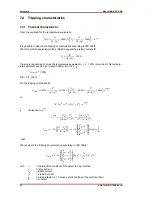
Page 52: ...ing is realized as soon as the temperature equivalent k2 100 is reached This tempera ture equivalent equals a permanent load current of k IB Trip k2 100 Trip k2 100 For the tripping characteristic 100...

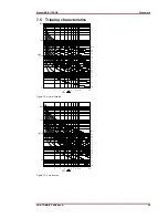
Page 53: ...B Woodward DOK TD MRI3 ITERE Rev A 53 7 4 2 Preload factor The normal tripping characteristic according to IEC 255 8 In I IB p l lB k Figure 7 1 Tripping characteristics for various preload factors p...

Page 54: ...ding to IEC 255 4 or BS 142 Normal Inverse type A 0 14 1 Very Inverse type B 13 5 1 Extremely Inverse type C 80 1 Long time inverse 120 1 RI inverse 1 0 339 0 236 RXIDG characteristic 5 8 1 35 Where t...

Page 55: ...igure 7 2 Normal Inverse Figure 7 3 Very Inverse 1 2 3 4 5 6 7 8 910 20 I IS 0 1 1 10 100 1000 t s tI 0 05 0 1 0 2 0 3 0 4 0 5 0 6 0 8 1 0 1 4 2 0 3 0 4 0 6 0 8 0 10 0 1 2 3 4 5 6 7 8 910 20 I IS 0 1...

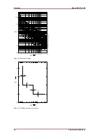
Page 56: ...7 5 Definite time over current relay 1 2 3 4 5 6 7 8 910 20 I IS 0 01 0 1 1 10 100 1000 t s tI 0 05 0 05 0 1 0 1 0 2 0 3 0 4 0 5 0 6 0 8 1 0 10 0 1 4 2 0 3 0 4 0 6 0 8 0 1 10 I IN 0 01 0 1 1 10 100 t...

Page 57: ...se Figure 7 7 RXIDG characteristic 1 2 3 4 5 6 7 8 910 20 I IS 0 1 1 10 100 1000 10000 t s tI 1 0 2 0 10 0 8 0 6 0 5 0 4 0 3 0 0 8 0 6 0 5 0 4 0 3 0 2 0 1 0 05 1 2 3 4 5 6 7 8 910 20 I IS 0 1 1 10 100...

Page 58: ...e 7 6 Output relays Contacts 2 change over contacts for relay 1 and 2 1 change over contact for relay 3 4 Technical data subject to change without notice 1 2 3 4 5 6 7 8 910 20 I IS 0 1 1 10 100 t s t...

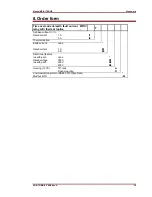
Page 59: ...rmal replica MRI3 T 3 phase current I I Rated current 1 A 5 A I1 I5 Thermal replica Earth current none Rated current 1 A 5 A E1 E5 Directional feature in earth path none Rated voltage 100 V in earth p...

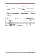
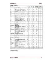
Page 60: ...te and should the occasion arise adjusted to the object item to be protected Setting of parameters System parameter MRI3 Function Unit type MRI3 IT ITE ITER Default Actual setting setting L1 L2 L3 Ipr...

Page 61: ...ase overcurrent element s X X X 0 06 I CHARI Reset Modus X X X I Pickup value for overcurrent high set element x IN X X X 1 00 tI Trip delay for overcurrent high set element s X X X 0 06 1 1 3pha e n...

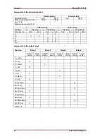
Page 62: ...ng No blocking Parameter set Set 1 Set 2 Set 1 Set 2 Set 1 Set 2 Set 1 Set 2 I X X I X X IE X X IE X X tCBFP X X Assignment of the output relays Function Relay 1 Relay 2 Relay 3 Relay 4 Default settin...

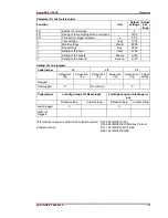
Page 63: ...e Minute m 00 Setting of the second Second s 00 Setting of code jumpers Code jumper J1 J2 J3 Default set ting Actual set ting Default set ting Actual set ting Default set ting Actual setting Plugged N...

Page 64: ...pen Germany Postfach 10 07 55 P O Box D 47884 Kempen Germany Phone 49 0 21 52 145 1 Internet www woodward com Sales Phone 49 0 21 52 145 216 or 342 Telefax 49 0 21 52 145 354 e mail salesEMEA_PGD wood...

Reviews: