


Manual
Manual 37223E
37223E
easYgen-3000
easYgen-3000 Series
Series (Package
(Package P1)
P1) -
- Genset
Genset Control
Control
©
© Woodward
Woodward
Page
Page 15/67
15/67
Screw Kit Installation
Screw Kit Installation
NOTE
NOTE
Don't drill the holes if you want to use
Don't drill the holes if you want to use the clamp fasteners. If the
the clamp fasteners. If the holes are drilled into the panel, the
holes are drilled into the panel, the
clamp fasteners cannot be used anymore!
clamp fasteners cannot be used anymore!
NOTE
NOTE
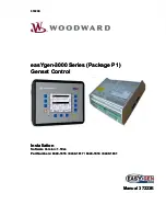
The housing is equipped with 12 nut
The housing is equipped with 12 nut inserts (refer to
inserts (refer to Figure 4-5
Figure 4-5 for their position), which must all be
for their position), which must all be
tightened properly to achieve the required degree of protection.
tightened properly to achieve the required degree of protection.
Some versions of the plastic housing are not equipped w
Some versions of the plastic housing are not equipped with nut inserts and may not be fastened w
ith nut inserts and may not be fastened with
ith
the screw kit.
the screw kit.
In order to enhance the protection to IP 66, it is possible to fasten the unit with a screw kit instead of the clamp
In order to enhance the protection to IP 66, it is possible to fasten the unit with a screw kit instead of the clamp
fastener hardware.
fastener hardware.
Proceed as follows to install
Proceed as follows to install the unit using the screw kit:
the unit using the screw kit:
1.
1.
Cut out the panel and drill
Cut out the panel and drill the holes according to the dimensions in
the holes according to the dimensions in Figure 4-5
Figure 4-5 (dimensions shown in mm).
(dimensions shown in mm).
2.
2.
Insert the unit into the panel cutout. Verify that the unit fits correctly in the cutout. If the panel cutout is not
Insert the unit into the panel cutout. Verify that the unit fits correctly in the cutout. If the panel cutout is not
big enough, enlarge it accordingly.
big enough, enlarge it accordingly.
3.
3.
Insert the screws and tighten to 0.6
Insert the screws and tighten to 0.6 Nm (5.3 pound inches) of t
Nm (5.3 pound inches) of torque. Tighten the screws with a crosswise
orque. Tighten the screws with a crosswise
pattern to ensure even pressure distribution.
pattern to ensure even pressure distribution.
NOTE
NOTE
If the thickness of the panel sheet exceeds 2.5 mm, be sure to use screws with a length of the panel
If the thickness of the panel sheet exceeds 2.5 mm, be sure to use screws with a length of the panel
sheet thi 4 mm.
sheet thi 4 mm.
Cut-out dimension:
Cut-out dimension:
249mm (+1,1mm) x 183mm (+1,0mm)
249mm (+1,1mm) x 183mm (+1,0mm)
249.0
249.0
183.0
183.0
5.
5.
0
0
254.0
254.0
24.5
24.5
124.5
124.5
224.5
224.5
21.5
21.5
91.5
91.5
161.5
161.5
194.4
194.4
259.0
259.0
5
5
.7
.7
ø 4.5
ø 4.5
12
12
x
x
Rmax:
Rmax:
R 4.0
R 4.0
Figure 4-5: Plastic housing - drill plan
Figure 4-5: Plastic housing - drill plan